.png)

While the time resolutions or speed of camera sensors have been improving through advancement in electronics, the imaging optics of such cameras have not changed for a long time. Today the imaging optics of ultrafast cameras, time-of-flight cameras, and depth cameras are simply inherited from the conventional photography optics of low-speed cameras. Such optics first conceived by Ibn al-Haytham almost a thousand years ago have evolved in terms of performance and capability but not in terms of principle. This unaltered incorporation of optics has overshadowed the true potential of new emerging sensors; especially ultrafast and depth-sensitive sensors. Since time and space (or time and depth) are conveniently interchangeable at ultrafast shutter speeds (time range less than 1 ns), the question arises whether the design of imaging optics for a high speed camera or depth sensitive camera should follow the same rules as conventional low-speed cameras. Would it be possible to use time instead of space when arranging optics? Can an ultrafast sensor benefit from a time-coded set of optics, each with dramatically different optical functionality? These are the fundamental questions that need to be answered as we advance in the fabrication of ultrafast and ToF sensors. This was the motivation of this study to discover, explore, and understand the new principles of designing optics in time.
Cavities and how they convert time to space
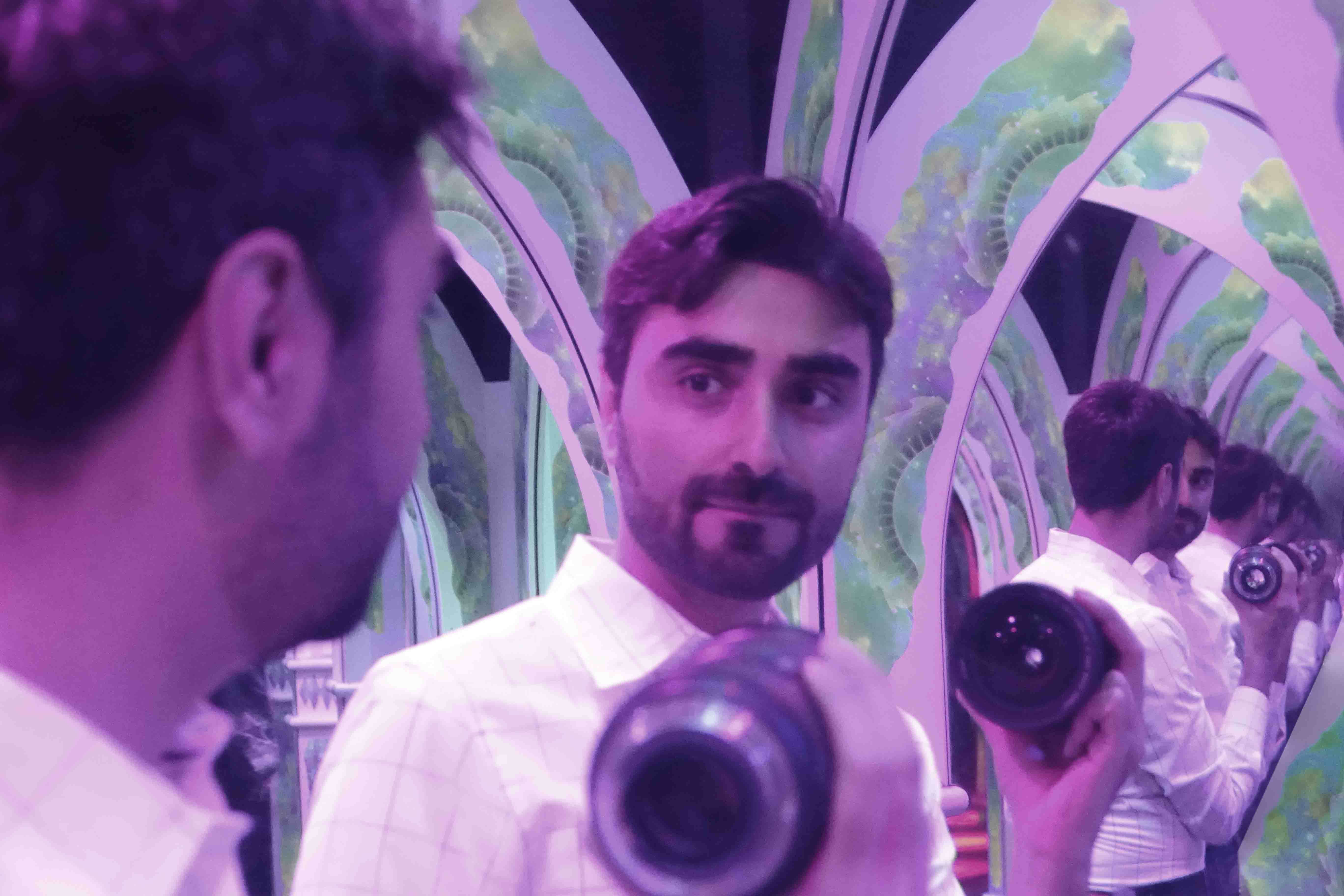
Standing in an infinity mirror you can see your repeating image over and over into infinite distance.
Infinity mirrors appear to do the impossible, they appear to recede back forever into darkness. In case you have never experienced an infinity mirror, you have likely experienced a similar effect looking into a mirror with a second mirror behind you in an elevator or a barber shop. Your reflection repeats over and over, retreating back in space. The infinity mirror gives the illusion of an enlarged space, a small room now looks like an infinite hallway. This simple construct of two mirrors facing each other is known as a Fabry-Perot (FP) cavity and is the most basic cavity that one can conceive. If the mirrors are chosen to be semi-reflective then at each roundtrip that light makes between the facets some portion of the light escapes out. FP cavity evolves the wavefront of the light, that is, it does not change the angle of the light rays that are circulating inside it after each round trip. Therefore, every round trip that light makes inside the cavity it is as if the light has actually travelled a longer distance in space and this is how cavity converts time to space for entering photons.
Key idea
In its simplest form, we found a way to design optics in time dimension and while doing so we found that many unconventional capabilities can be realized by leveraging this dimension. This is done by introducing a cavity into conventional photography optics and using a fast or depth-sensitive sensor. The cavity is partially reflective, and partially transmissive (just like the infinity mirror we discussed in the introduction). Some of the light will pass right through the cavity to the sensor, some light will bounce in the cavity once, twice, etc times before reaching the sensor. You can imagine that the cavity is like an infinity mirror, repeating your reflection multiple times at different times. The key insight is that we can modify or evolve the captured wavefront during each roundtrip in the cavity and then record it at the "right time". But due to arrangement of optics this "right time" is equivalent to "right distance", "right color", "right zoom", "right focal length" or any other desired optical functionality that was previously achieved by having physical distances or arrangements in front of the sensor. The study explores and demonstrates few of these possibilities.
Compressing lenses by folding focal length in time
Think about the infinity mirror example, in that example we were able to increase the perceptive size of a small room. Now if we think about a camera lens, the lenses goal is focus the light entering the camera on a small sensor. In order to focus the light, the lens needs to be at a set distance from the sensor based on thin lens equation (1/f=1/o+1/i where f is focal length o is object to lens distance and i is image to lens distance). Imagine if we placed our infinity mirror in this space between the lens and the sensor. This would increase the perceptive distance between the lens and camera allowing the lense to be brought much closer to the sensor. This is exactly what we did, except instead of an infinity mirror, we placed a cavity consisting of two partially reflective mirrors between the focusing lens and the sensor. With each roundtrip in the cavity, the image become more and more focused. We can retrieve the focused image by only looking at the time frame associated with the distance the lens requires. In experiments we were able to decrease the lens-sensor distance or lens axial size by an order of magnitude (see publication link).
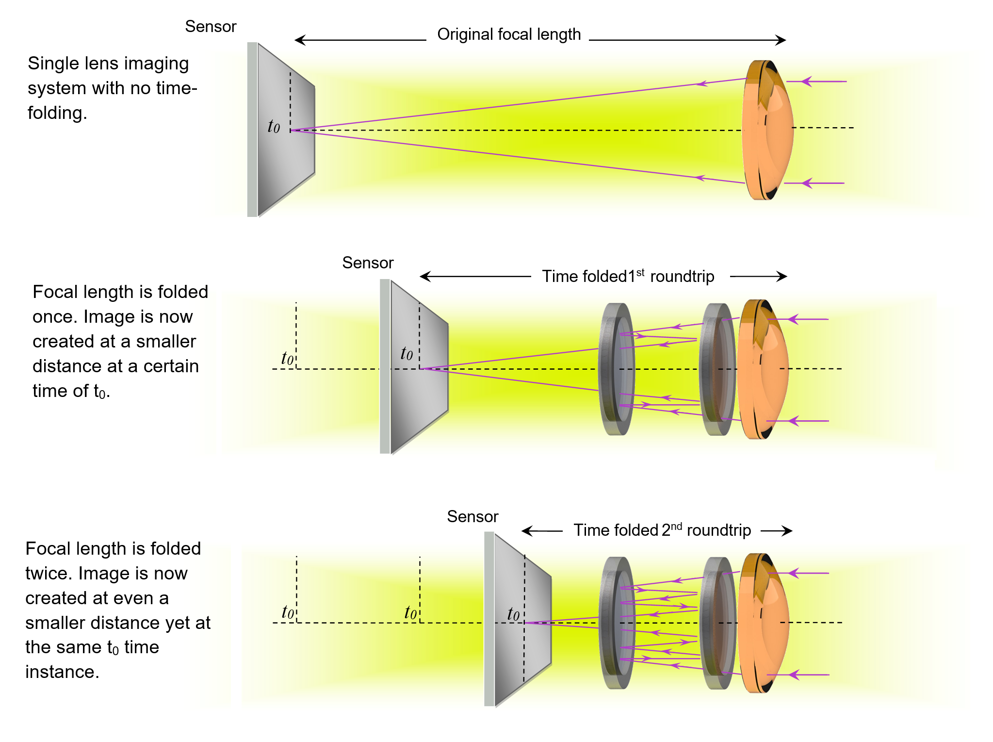
Time-folding can fold the lens-sensor distance into significantly smaller distances. The focal length can be mapped into time t0 and this time instance can be accessible at much smaller physical distance than what thin lens equation enforced.

Using time-folding the "MIT" Image is captured at 1/10th of the physical lens-sensor distance conventionally enforced by thin lens equation.
Multi-zoom capture enabled by time-folding
If you wanted to capture both a wide angle and zoomed in video of a scene you traditionally had two choices. You could either use two cameras, or crop your wide angle image after the fact at the cost of resolution. How ever in time dimension a multi-zoom capture is possible by placing the focusing lens inside of the cavity. During each round trip inside of the cavity, the light will pass through the lens twice more, effectively changing the focal length (zoom and magnification factor). We call this optics a multi-zoom optics because depending on the time of the acquisition the magnification can drastically change.
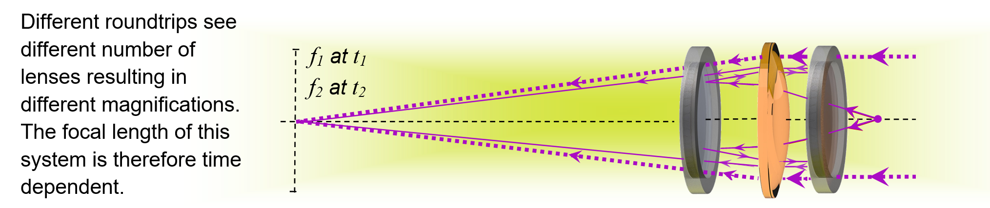
Time-folding enables multi-zoom acquisition, a time-folded lens can capture images much closer than its original focal length at the right time.
Multispectral imaging enabled by time-folding
In the previous two examples we had a cavity to alter the focusing aspects of the imaging system. It turns out we can also use cavities to alter other aspects of the system such as enabling multispectral imaging. Recall the the cavity repeats the signal on the sensor at a regular time interval. Imagine you are back inside the infinity mirror with a super fast clock in your hand but this time instead of having only two parallel half-mirrors that form the cavity you have three half mirrors. Now imagine that the half-mirrors behind you is a silver mirror and reflects all the colors but the first half-mirrors ahead of you reflects only red and is transparent to other colors, right after that red mirror there is another half-mirror that only reflects blue. Now what will happen when you have a colorful scene inside the cavity. When you look at your clock you will see that the red points of the scene will repeat with faster repetition rate than blue and this way you can correlate the time of repetition with color thus making a multispectral recording of the scene.
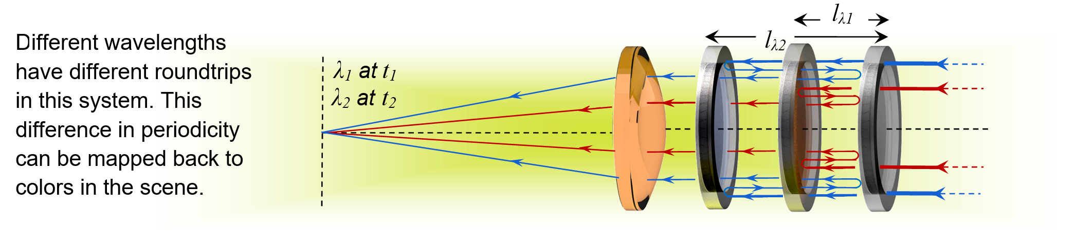
Time-folding enables multi-spectral acquisition. See publications for detailed results.

The letters A and B have different colors and thus blink at different times after passing through time-folded optics, the periodicity of blinking is used to extract wavelength information.
There are many other applications and architectures that can branch from the concept of time folding, for example one can sample the light-field evolving in the optical system using time-folding as seen below.
Time-folding enables capturing cross sections of the light-field evolving in the optics of the camera or in the scene. The example above shows how time-folding can realize ultrafast focal stack imaging. Each line is a cross section of the light passing through the optics. Frames are showing different x-t cross sections at different y values.
B. Heshmat*, Matthew Tancik, Guy Satat, Ramesh Raskar, "Photography optics in the time dimension", Nature Photonics, Vol 13, 2018. doi:10.1038/s41566-018-0234-0
The datasets generated during and/or analyzed during the current study are available from Barmak Heshmat the corresponding author on reasonable request.
If you have a new applications and would like to license this technology please contact Daniel Dardani at MIT technology licensing office: ddardani@mit.edu
This technology is patented under: US Patent B. Heshmat, M. Tancik Time-folded imaging; Methods and Apparatus for Imaging Using Optical Cavity, 15682145, (2017).
MIT News: Photography in time dimension(13 Aug 2018)
LiveScience (coming soon)
What are the applications of this technology?
Broadly speaking time-folding can impact any imaging system that deals with optically capturing depth information or time information. We demonstrate that it is possible to reduce the length of the lens system by an order of magnitude using time-folding. This is useful for creating smaller camera lenses or mapping satellites. We also demonstrated that it is possible to image at two different focal lengths at the same acquisition. This can be useful in applications where both a wide angle view and a zoomed view are captured at the same time (without loss of resolution, or the need to change lenses) For example, optical coherence tomography (OCT) systems, interferometric imaging systems, and photocytometry systems can benefit from this. In our final demonstration, we showed multi-spectral ultrafast imaging. This has applications in fluorescence lifetime imaging and it enables multispectral imaging without having to change filters. In addition to our demonstrations, this technique can be applied to other types of imaging for various applications such as time-resolved ellipsometric or focal stack imaging. One of the most common time-of-flight sensors currently is used in LIDAR which is used in multiple robotics and navigation applications including autonomous cars. Time-folded optics could find a use in those applications.
What is the cost of the system?
The cost of this system depends on the hardware specifications. Our technique is a general and broad new perspective that can be applied to varieties of systems with different costs. The optics itself can be as cheap as few tens of dollars but the imaging sensor is the main cost component. If you want to use ultrafast system with high time resolution the setup cost can be as high as 500K$; if you are using an electronic single photon diode array (SPAD) camera the cost can be around 50K$; and if you use a continuous wave time-of-flight camera the sensor cost can be as low as 50-500$.
What is time-folding?
Time-folding is the act of folding spatial optical path into time in order to encode a desired information from the scene or functionality from optics into time of acquisition. One can time-fold distances, wavelengths, polarizations or even time-fold an entire transfer function by placing optics inside a cavity. Time-folding makes optics time-dependant so at different times the optics has different response function or modulation transfer function (MTF). As our study proposes for the first time, such conversion can be done by varieties of cavities and using the Fabry-Perot cavity is the most basic way to do time-folding. During each round trip in the cavity, some of the light escapes the cavity and is captured on the sensor. The sensor is able to distinguish different round trip outputs of the cavity and thus recover the original information.
What's new about time-folding?
Time-folding is a new way of designing photography or imaging optics by leveraging the duality between time and space. The technique enables unconventional arrangement of optics (for example placing a lens 10 time closer to the sensor than its physical focal length) which can provide a certain desired functionality at a specific time.
What is an ultrafast camera?
A typical cell phone will capture a video with a frame rate of 30 frames per second (fps). The high speed cameras that are able to capture phenomenon such as a bullet firing have frames rates ranging from 500 - 25000fps. The ultrafast cameras we are talking about have frame rates in the range of 1,000,000,000,000fps. At this speed it is possible to image light as it propagates through space! These cameras work by illuminating the scene with a very quick laser flash followed by a precisely timed camera capture. These cameras are becoming more and more commercially available. Most concepts introduced in our study can be also used by continuous-wave depth cameras or time-of-flight cameras, commercially used in game interfaces, autonomous cars, and mapping equipments.
What was the genesis of this technique?
Time-of-flight imaging has conventionally been used in imaging fast phenomena (Ultrafast imaging) and imaging in complex geometries (such as around the corner and through diffusers). There were a lot of research on how to better resolve the scene using time information or computational methods but there was no notion of what can be done with the optics of imaging itself in the time dimension.
How does this work relate to the 'optical brush' and 'Reading through closed books' from camera culture group? In principle we use the similar ultrafast imaging sensor to extract the signal we are looking for. By inspecting the temporal profile of our signal, we are able to infer properties of the scene or achieve functionalities from our optics that are impossible to retrieve using only spatial information. The previous works were focused on one specific challenging application such as reading through closed book or imaging around the corner but this work is more at the fundamental level and it can impact the design of optics for any time-resolved system.
What are the limitations of the current first demonstration? The optical alignment of the cavity is sensitive. If the optical components are not coaxial, the signal can escape the cavity. In the future we envision optical components designed for this use. For example, a single piece of glass can be coated on both side creating a high accuracy cavity. This would constrain the reflective components preventing them from going out of alignment. The loss of signal at higher roundtrips is another drawback; e.g. if your applications require 10 or more round trips in the cavity then your signal level is going to be reduced notably after those many round trips since cavities can be lossy. Having said that there are plenty of possibilities even with first initial round-trips as demonstrated in the paper.
What's next for you and your colleagues as you move forward with this technology? Are there any plans to enhance the technique, or other avenues or applications you'd like to explore?
There are endless possibilities with time-folding, for us it is as if we have found a new way to think about optical imaging at a very fundamental level. There are four core paths lying ahead of time-folding technology: 1- designing imaging optics with radically better capabilities. Examples of this category is ultracompact optics, SNR enhancement by time folding large aperture long-focal length lenses, etc. 2- Realizing higher order time-folding by improving the cavity quality factor or reducing its loss. Examples of projects on this direction can be enhancing the cavity elements materials or using polarization to reduce loss of each roundtrip. 3- Considering new categories of cavities for realizing more complex functionalities or enabling time-folding for non time-sensitive sensors. For example, one can use evanescent cavities, ring cavities or nonlinear cavities to acquire new types of information about the scene. 4- Using phase instead of time to realize the same functionalities and architectures. Examples on this direction can be using a specific type of cavity combined with interferometric imaging to encode a desired information into phase.
Can a normal camera be enhanced by time-folding?
Not with the architecture presented in this study. A normal camera doesn't have the speed or depth sensitivity to resolve each roundtrip and thus the output results would be an integration of all round trips. But this is a great challenge to be thinking about and might be addressable with computational techniques or other types of cavities.
For starters, how does this going to impact our lives?
Time-folding impacts the design of optics in time or depth sensitive cameras such as those used in autonomous navigation, aerial mapping, commercial gaming consoles, VR/AR headsets and many other applications that rely on time-of-flight or depth or ultrafast cameras. Time-folded optics can compress the size of those optics, enable capturing color as well as depth information, or even enhance SNR in a given formfactor.
Typically our readers are interested in emerging technologies and how they might affect the medtech realm. Could you talk a little about any medical device or technology applications?
We have demonstrated multispectral imaging using time folding which can be used for fluorescence lifetime imaging. Another potential application is impacting optics of optical coherence tomography or OCT systems with time-folding. There is a wide range of possibilities to leverage time-folding to improve magnification or enable a nonconventional functionality.
| The future of imaging | THz waves and inspection of cultural samples | Imaging at trillion frames per second |
 |
 |
 |
1.Redo-Sanchez, A. Heshmat, B. et al. Terahertz time-gated spectral imaging for content extraction through layered structures. Nat. Commun. 7, 12665 (2016).URL, MIT News. BBC,
2.Satat, G., Heshmat, B. et al. Locating and classifying fluorescent tags behind turbid layers using time-resolved inversion. Nat. Commun.6, 67961–67968 (2015).
3.Satat, G. et al. Locating and classifying fluorescent tags behind turbid layers using time-resolved inversion. Nat. Commun.6, 67961–67968 (2015).
4. B. Heshmat, I. H. Lee, R. Raskar, "Optical brush: Imaging through permuted probes", Nature Scientific Reports, Vol. 6, 20217, (2016),URL, MIT News
5.Gariepy, G. et al. Single-photon sensitive light-in-fight imaging. Nat. Commun. 6, 6021 (2015).
6. A. Velten et al., Recovering three-dimensional shape around a corner using ultrafast time-of-flight imaging. Nat. Commun. 3, 745 (2012).
1.Shen, Y.-C. Terahertz pulsed spectroscopy and imaging for pharmaceutical applications: a review. Int. J. Pharm. 417, 48–60 (2011).
2. Goda, K., Tsia, K. K. & Jalali, B. Serial time-encoded amplified imaging for real-time observation of fast dynamic phenomena. Nature 458, 1145–1149 (2009).
3. Gao, L., Liang, J., Li, C. & Wang, L. V. Single-shot compressed ultrafast photography at one hundred billion frames per second. Nature 516, 74–77 (2014).
4. Goda, K. & Jalali, B. Dispersive Fourier transformation for fast continuous single-shot measurements. Nat. Photonics 7, 102–112 (2013).
5. Li, L., Wang, D., Liu, C. & Wang, Q.-H. Ultrathin zoom telescopic objective. Opt. Express 24, 18674 (2016).
6. Bahrami, M. & Goncharov, A. V. All-spherical catadioptric telescope design for wide-field imaging. Appl. Opt. 49, 5705 (2010).
We would like to thank Prof. Moungi Bawendi and his team members Daniel Franke and Jason Jungwan Yoo at the MIT Department of Chemistry for their generous help with preparation of fluorescent samples. Authors also thank Ayush Bhandari and Kari Pulli for discussion with regards to matrix representations and manuscript proofreading.
