Optical brush
Optical brush is an open-ended bundle of optical fibers that is enabled with time of flight technology to image and sense through complex environments. This imaging interface allows fibers to penetrate through barriers and complex geometries to sense and image in conventionally unreachable areas.
A set of reference clock pulses of light is delivered to the fibers that enable full localization of each fiber in the sensing medium. This allows the large number of fibers to move freely in the sensing environment. Each fiber delivers another signal from the scene or medium. By merging the location of each fiber and the signal that each fiber measures an image is reconstructed independent of the permutation of the fibers.
Access the paper:
Barmak Heshmat, Ik Hyun Lee, Ramesh Raskar, “Optical brush- imaging through permuted probes” Nat. Sci. Rep., www.nature.com/articles/srep20217
News Stories
MIT News: Imaging with an optical brush (12 Feb 2016)
Science Daily: Imaging with an optical brush (12 Feb 2016)
Gizmag: Lensless imaging achieved using optical brush (14 Feb 2016)
Frequently Asked Questions
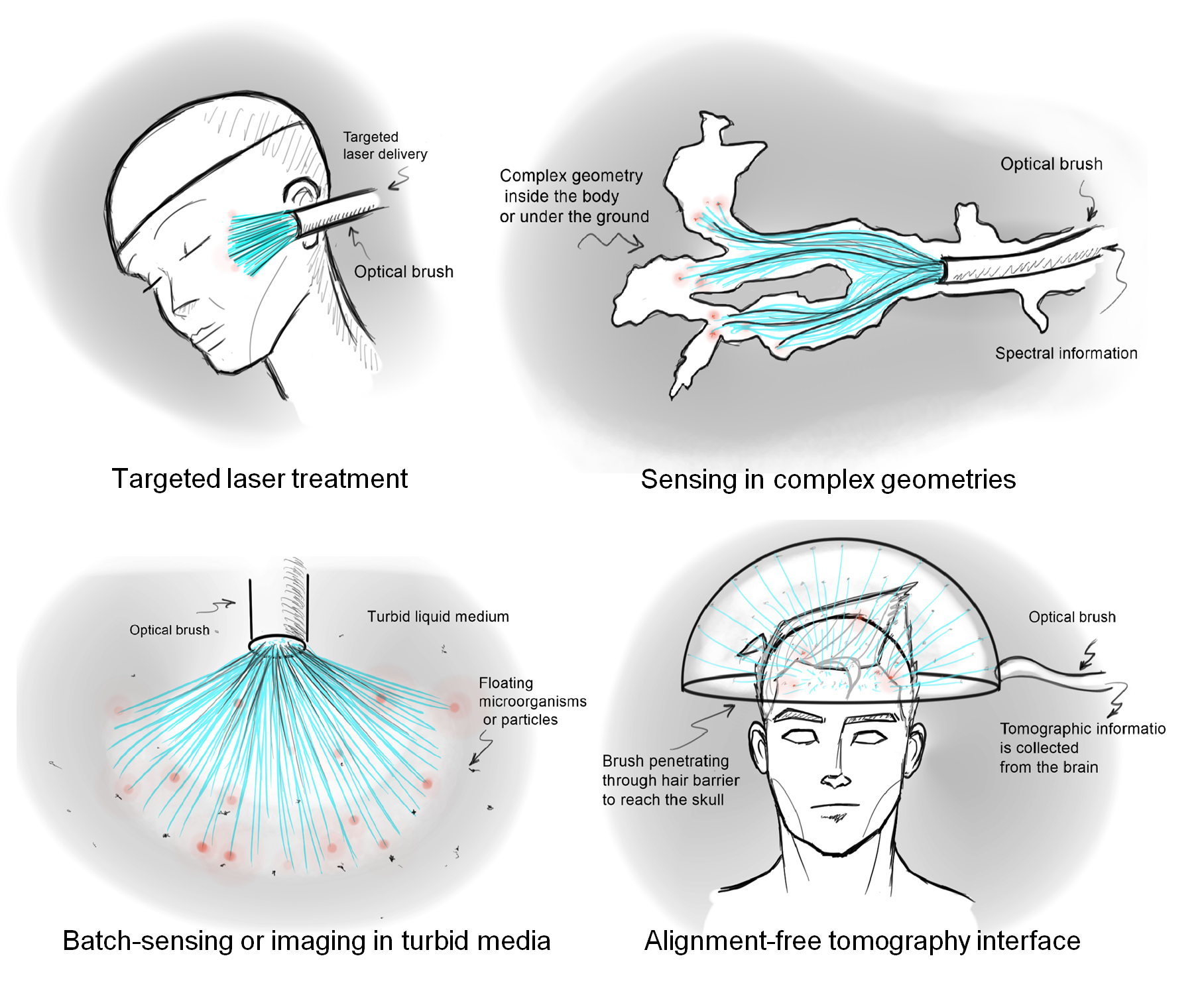
What are the applications of an optical brush? Optical brush is a sensing interface fully based on optical fibers. Fibers are well known for sensing in harsh environment, they are flexible, have no EM noise and are intrinsically water proof. The optical brush provides a flexible form factor along robust sensing that is needed in harsh environment and complex geometries (e.g. inside the body, underground, and inside industrial turbid media. See potential applications below:

What’s new about optical brush? Optical brush takes the theory of imaging into a fundamentally new direction. Unlike conventional lens-based imaging and parallel-map imaging, optical brush images based on a random map between scene points and sensor pixels. This provides a nonuniform sampling scheme that can be beneficial for imaging complex geometries. The pixels of this imaging interface can be physically separated apart and distributed into an environment.
What is the cost of an optical brush? The major cost for optical brush is the calibrating ToF technology that is used for it. As discussed in the paper, this can significantly vary depending on the application. Larger settings tend to allow cheaper calibration technologies and thus lower cost.
How does this work relate to trillion FPS imaging from camera culture group? We use the similar ultrafast imaging camera at the back of the brush to read the location signals of each fiber. Based on the measured time of arrival we calculate the location of each fiber.
What are the limitations of current first demonstration? Low spatial and temporal resolution; The resolution can be improved by using more fibers or by resolving more pixels through each fiber. Both of these limitations are not fundamental. Another limitation is reference delivery to the fibers. Delivering reference time signal to the fibers is currently forcing us to use a synthetic scene. More advanced referencing can be used to eliminate the side references and deliver the reference localization signal through the fibers themselves. Another limitation is the time resolution of the setup. Higher time resolution can provide better spatial resolution for calibration. Our method does not currently support real-time applications.
How will these complicated instruments transition out of the lab?
The size and cost of an optical brush depends on the core ToF technology that is used. Several emerging technologies (e.g. SPAD cameras and CW ToF) are likely to reduce the cost and size of ToF measurements.
What’s next for optical brush? Optical brush is a first step toward micro scale imaging sensor networks. We are looking for collaborators to adapt other technologies for self-calibration of optical brush. Another direction would be realization of real-time self calibration.
Extended abstract
We exploit time of flight (ToF) measurements to enable a flexible interface for imaging through a permuted set of fibers. The fibers are randomly distributed in the scene and are packed on the camera end, thus making a brush-like structure. This realizes a sensing image with a non-parallel or incoherent mapping between secene points and sensor pixels which is a stretch of the imaging apperatus concept at a very fundamental level.
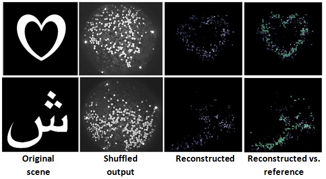
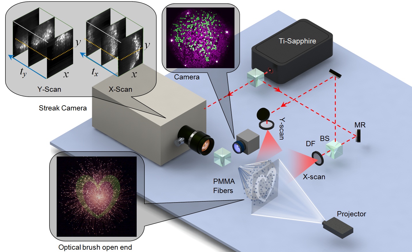
Based on our setup illustrated above the scene is illuminated by two off-axis optical pulses. Temporal signatures of fiber tips in the scene are used to localize each fiber. Finally, by combining the position and measured intensity of each fiber, the original input is reconstructed. Below you can see the results for 1100 fibers that are optically sorted with this technique to reconstruct the image.
 Unlike conventional fiber bundles with packed set of fibers that are limited by a narrow field of view (FOV), lack of flexibility, and extended coaxial precalibration, the proposed optical brush is flexible and uses off-axis calibration method based on ToF. The enabled brush form can couple to other types of ToF imaging systems. This can impact probe-based applications such as, endoscopy, tomography, and industrial imaging and sensing in harsh enviroments.
Related Talks:
The talk below discusses future technologies and methodologies for imaging and sesning.
Related Work
1. K. Bremer et al., Fibre optic pressure and temperature sensor for geothermal wells. 2010 IEEE Sensors, 538–541 (2010).
2. P. R. Fernández et al., Differential binary encoding method for calibrating image sensors based on IOFBs. Sensors. 12, 4133–4155 (2012).
3. P. Kim et al., In vivo wide-area cellular imaging by side-view endomicroscopy. Nat. Methods. 7, 303–5 (2010).
4. S. Yang, B. Zhou, T. Sun, K. T. V Grattan, A Novel Optical Sensor Platform Designed for Wireless Sensor Networks. J. Phys. Conf. Ser. 450, 012007 (2013).
5. A. Velten et al., Recovering three-dimensional shape around a corner using ultrafast time-of-flight imaging. Nat. Commun. 3, 745 (2012).
6. S. V Patwardhan, J. P. Culver, Quantitative diffuse optical tomography for small animals using an ultrafast gated image intensifier. J. Biomed. Opt. 13, 011009.
7. C. Dunsby, P. M. W. French, Techniques for depth-resolved imaging through turbid media including coherence-gated imaging. J. Phys. D. Appl. Phys. 36, R207–R227 (2003).
8. G. Satat, et al., Locating and classifying fluorescent tags behind turbid layers using time-resolved inversion, Nat. Commun. 6, 6796,(2015).
Acknowledgements
The authors like to acknowledge technical support from Mahdad Hosseini Kamal at EPFL, Hisham Bedri, Achuta Kadambi and Sang-won Leigh at MIT Media Lab, Dr. Mark Wilson and Prof. Bawendi at MIT Dept. of Chemistry.
This is the end of media page.
.png)


