
Cardboard Springs
Sspringy is a series of simple toys, made out of cardboard that exhibit funny looking oscillatory motion. They're based on Sarrus linkage implemented using compliant joints.
Buildlog
First version
At first I just put it together using scotch tape.
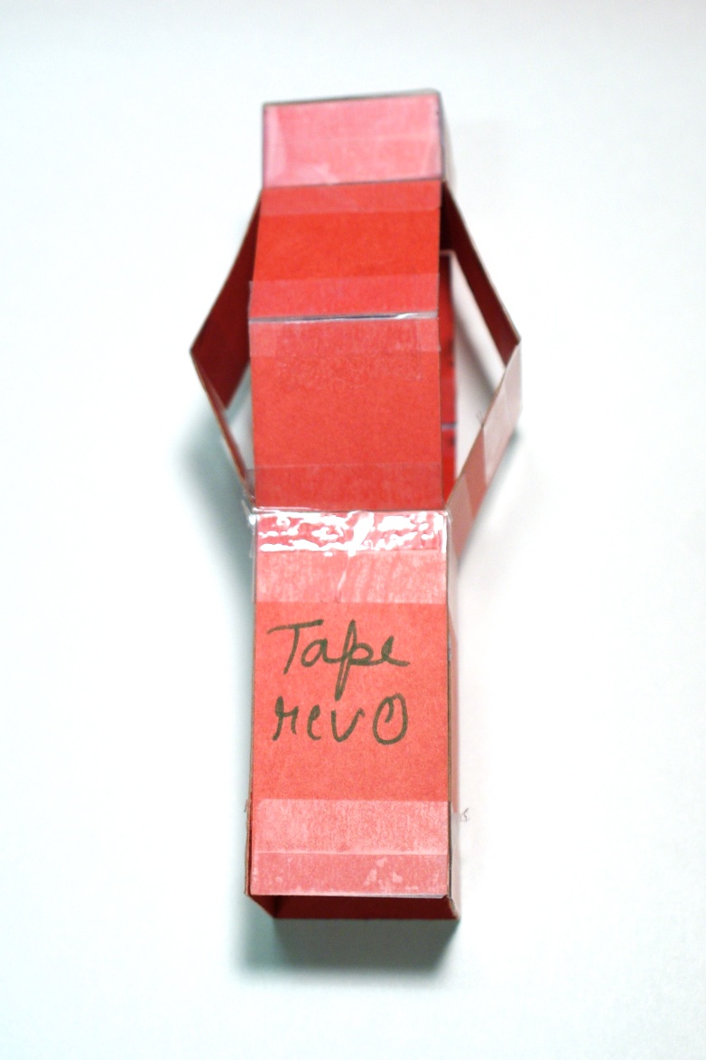
The First springy ever!
However, the tape creates a couple of problems.
-Its difficult to reproduce the same behaviour by manually taping the joints
-Scotch tape joints start to break after an hour or so of playing with
-Also it looks ugly!
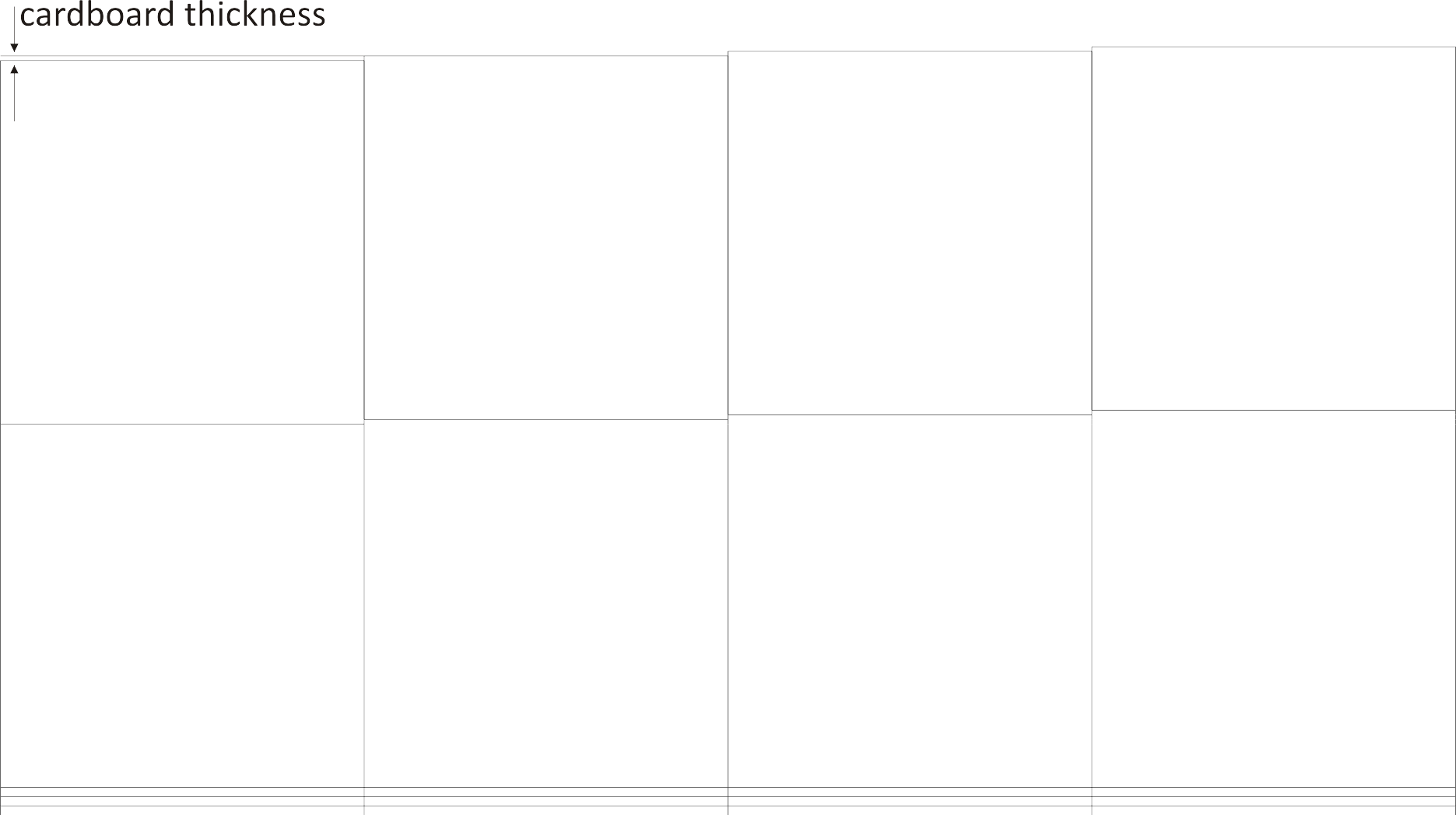
-The thickness of the cardboard becomes significant when the top folds are stacked together.
Concept sketchesSome mundane everyday life things, that sspringys could potentially bring some fun to.
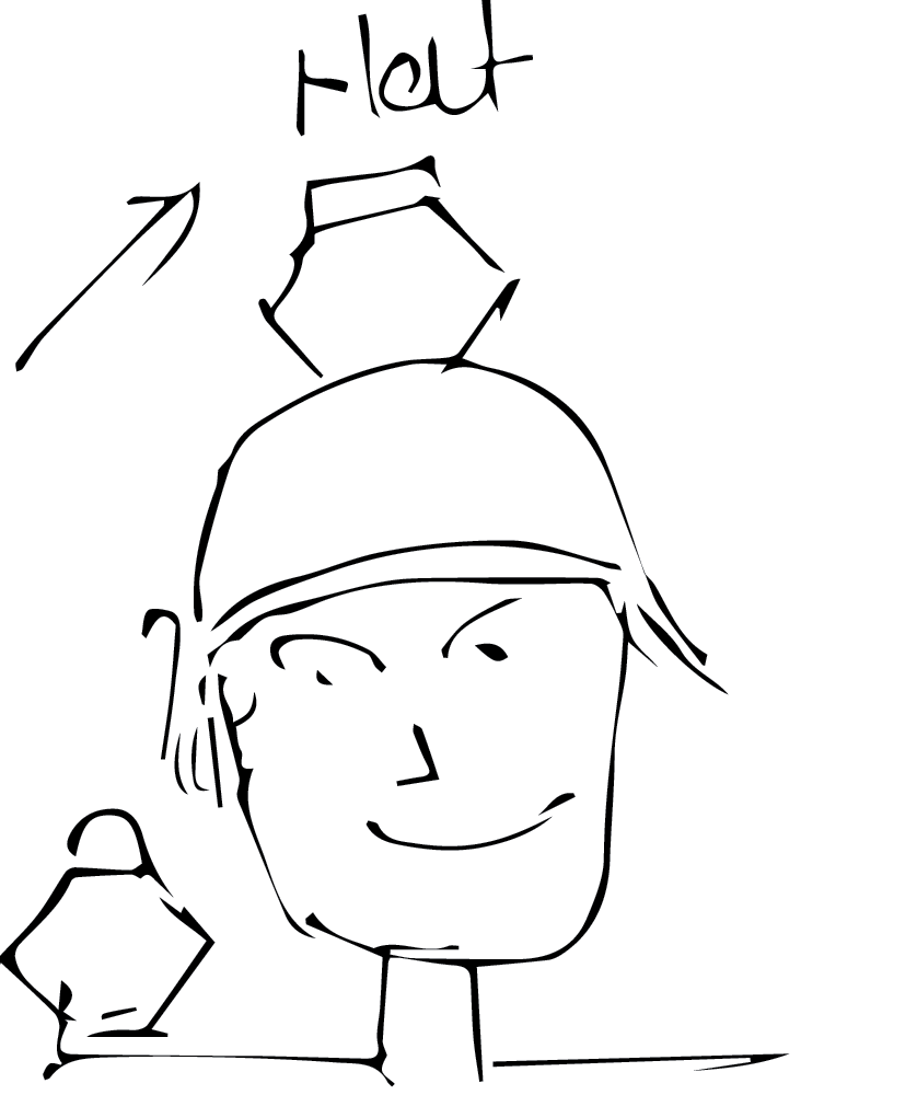
Wear it on your hat, Or just walk around with a pet sspringy!
Oh and it bobs with your walk.
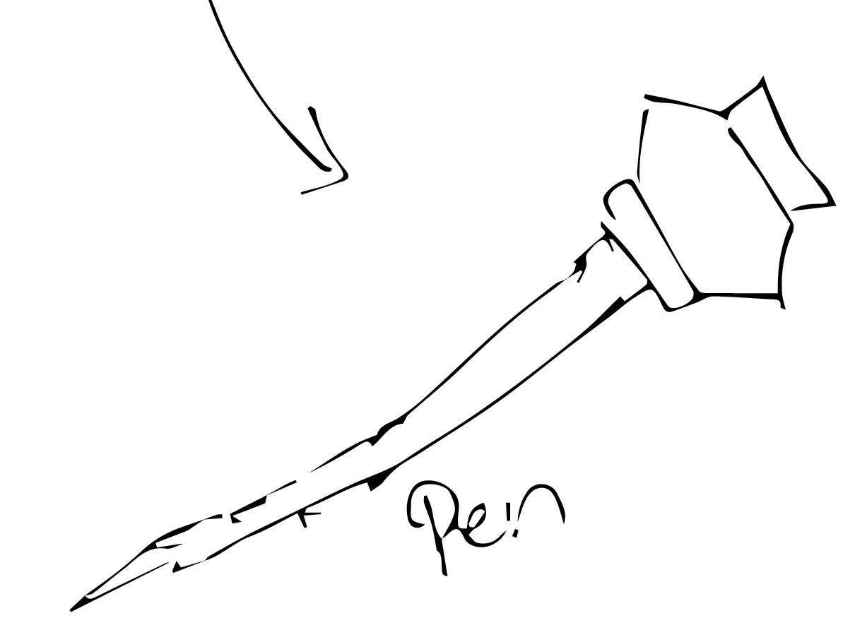
Put it on your pen.
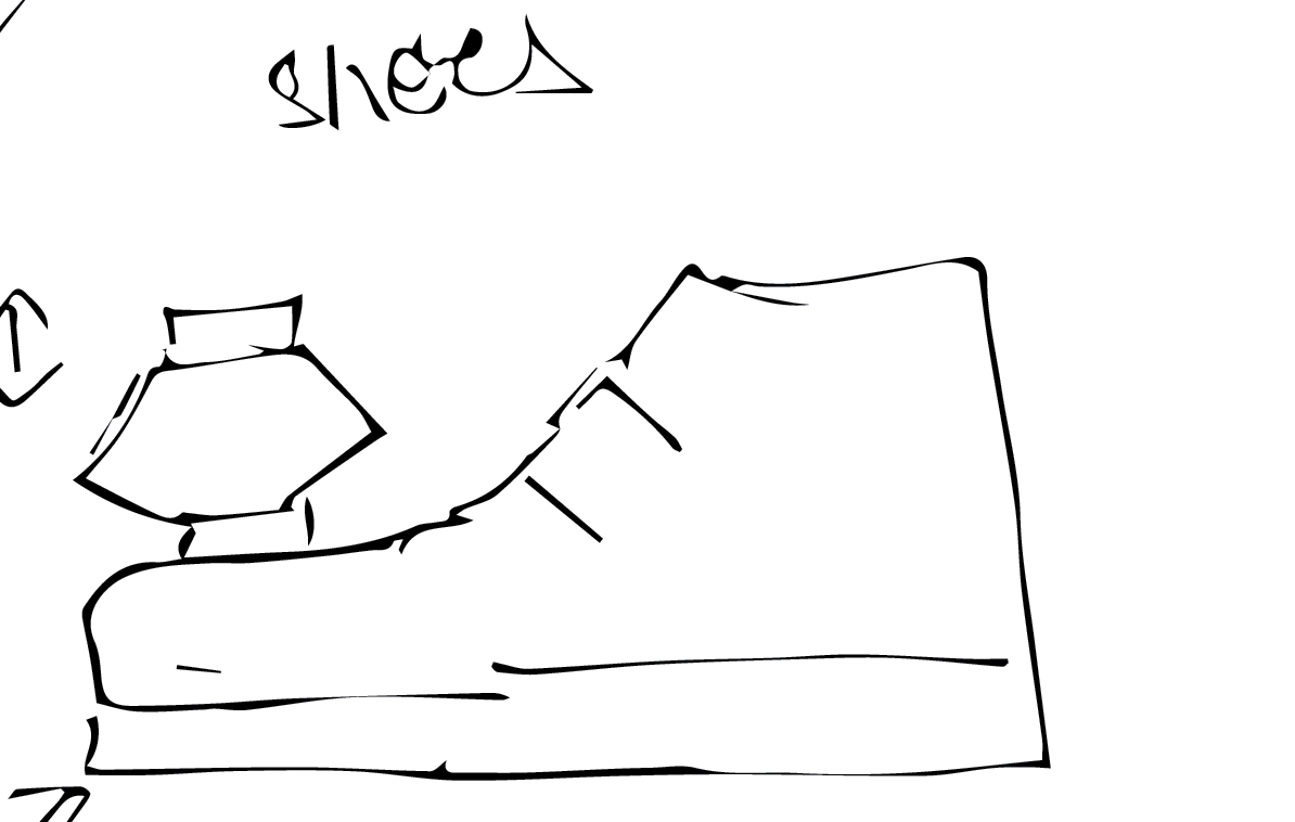
Or let it ride your shoe
Revision1: Dashed cut joints
To improve on the first version, I tried using four parallel dash-ed cut lines for the complaint joint.
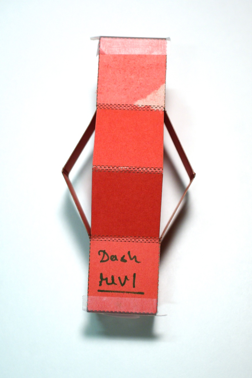
Revision1
The dashed cuts allow for excellent control over fold lines!
This design presents some problems too.
-I was expecting multiple dashed cuts to share the load of the joint, but in practice all compliance seems to come from just one line
-Though, more easy to reproduce than manually taping joints, the elasticity of the dashed joint seems to be quite dependant on the history of its use. Which becomes evident the first time the joints are actuated: the mechanism doesnt return to its original state.
-The thickness of the carboard was taken into account for the top flaps
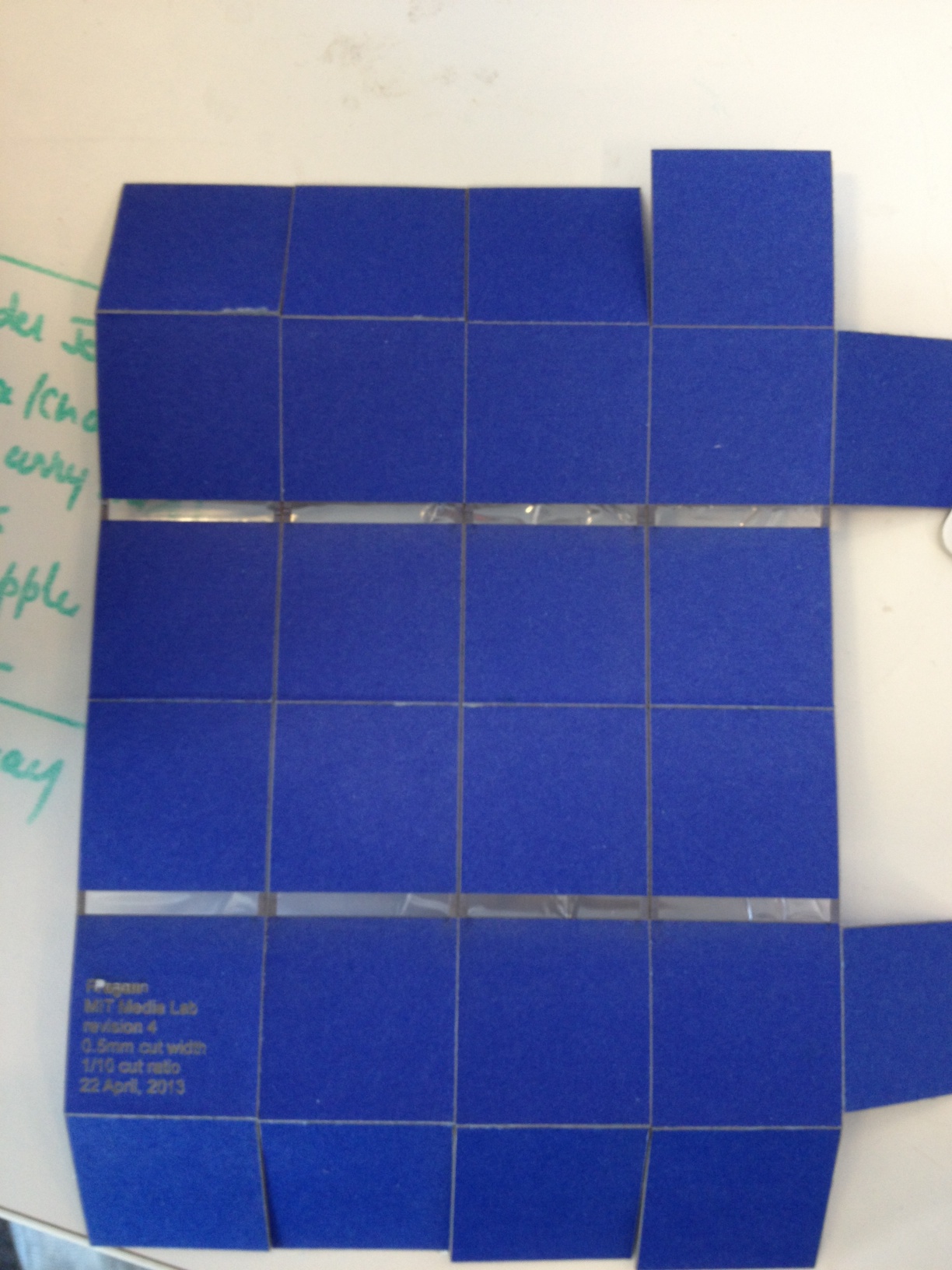
I looked at several other similar projects and found that plastic laminates are quite commonly used in cardboard compliant joints. I found that I could just use a regular document lamination machine with my 6-ply cardboard. Furthermore, the lamination sheets seemed to adhere to my cardboard really well. Which basically meant that the laminate would stay even if I laminated just one side of the cardboard.
Armed with all these primitives, I replaced dashed cuts with scores.
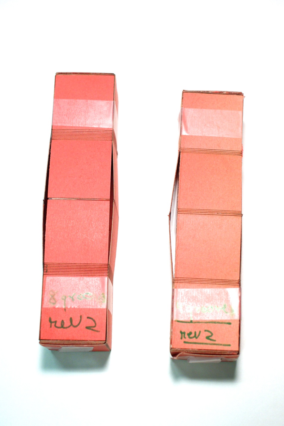
Revision2
Rev2 has very good resilience, reproducibility and good elastic response with next to none hysteresis.
Some of problems/observations with rev2
-As the middle hinge opens outwards, multiple score lines on the hinge reduce reproducibility slightly (right). This was fixed in another subrevision (left) by reducing the number of middle hinge score lines to two.
-The torsion springs formed at the top and bottom hinges are much more stronger in comparison to the forces produced by the weight of structure itself, so the structure doesn't oscillate by itself.
-Occasionally one of the four hinges enters an inverted state where the middle hinge moves inside the structure.
-Solidworks was giving a lot of trouble going through the huge number of constraints between line segments of the sketch.
Revision3: To Python from Solidworks
In revision3, the design remained the same as rev2. I moved from solidworks to python to generate toolpath files, hoping to get a tighter control over some parameters I wanted to play with. I usd the library svgwrite to generate svg files.
Here's the python program used to generate the svg files for rev3.
import svgwrite
from svgwrite import cm, mm

side = 40
num_sides = 4
num_panels = 6
thickness=0.5
length = side*num_panels + (4*thickness)
num_cuts = 10
cut_width = 0.6


dwg = svgwrite.Drawing(filename='basic_box.svg', debug=True)
cuts = dwg.g(id='cuts', stroke='black')
scores = dwg.g(id='scores', stroke='red')
dwg.add(cuts)
dwg.add(scores)

def basic_box():
	start_x = 0
	end_x = 0
	top_cut = 0
	bottom_cut = 0
	reference_height = 2*side
	for i in range(num_sides):
		end_x = start_x + side
		(top_cut,bottom_cut) = addSide(dwg,start_x,end_x,i,reference_height)
		start_x = start_x + side
	lastSide(dwg,start_x,top_cut,bottom_cut,reference_height)
	dwg.save()


def addSide(dwg,start_x,end_x,count,reference_height):
	"""I add horizontal cuts for each side to each panel
	"""
	#Leave for thickness
	#All sides meet at the hinges, so we take the top hinge as the reference
	top_hinges = []
	top_hinges_bottom = 0
	top_hinges_top = reference_height
	for i in range(num_cuts):
		top_hinges_bottom = reference_height + (i*cut_width)
		top_hinges.append(top_hinges_bottom)
	top_fold = top_hinges_top - side + (thickness*count)
	top_cut = top_fold - side
	mid_hinge = top_hinges_bottom + side
	bottom_hinges = []
	bottom_hinge_top = mid_hinge + side
	for i in range(num_cuts):
		bottom_hinge_bottom = bottom_hinge_top + (i*cut_width)
		bottom_hinges.append(bottom_hinge_bottom)
	bottom_fold = bottom_hinge_bottom + side + (count) * thickness
	bottom_cut = bottom_fold + side

	cuts_arr = [top_cut,bottom_cut]
	scores_arr = [top_fold,mid_hinge,bottom_fold]+top_hinges+bottom_hinges
	for y in cuts_arr:
		cuts.add(dwg.line(start=(start_x*mm,y*mm), end=(end_x*mm,y*mm)))
	for y in scores_arr:
		scores.add(dwg.line(start=(start_x*mm,y*mm), end=(end_x*mm,y*mm)))

	#If this is the first side, then cut otherwise score
	if count == 0:
		cuts.add(dwg.line(start=(start_x*mm,top_cut*mm), end=(start_x*mm,bottom_cut*mm)))
	else:
		scores.add(dwg.line(start=(start_x*mm,top_fold*mm), end=(start_x*mm,top_hinges_top*mm)))
		cuts.add(dwg.line(start=(start_x*mm,top_hinges_top*mm), end=(start_x*mm,bottom_hinge_bottom*mm)))
		scores.add(dwg.line(start=(start_x*mm,bottom_hinge_bottom*mm), end=(start_x*mm,bottom_fold*mm)))
		cuts.add(dwg.line(start=(start_x*mm,top_cut*mm), end=(start_x*mm,top_fold*mm)))
		cuts.add(dwg.line(start=(start_x*mm,bottom_fold*mm), end=(start_x*mm,bottom_cut*mm)))
	return (top_cut,bottom_cut)


def lastSide(dwg,start_x,top_cut,bottom_cut,reference_height):
	#Add tabs
	tab_length = side - (thickness*num_sides)
	end_x = start_x + tab_length

	top_hinge = reference_height
	top_tab_bottom = top_hinge
	top_tab_top = top_tab_bottom - tab_length
	bottom_tab_top = top_hinge + side + side + (num_cuts*cut_width*2)
	bottom_tab_bottom = bottom_tab_top + tab_length

	arr = [top_tab_top,top_tab_bottom,bottom_tab_top,bottom_tab_bottom]
	for y in arr:
		cuts.add(dwg.line(start=(start_x*mm,y*mm), end=((end_x*mm,y*mm))))

	cuts.add(dwg.line(start=(end_x*mm,top_tab_top*mm), end=((end_x*mm,top_tab_bottom*mm))))
	cuts.add(dwg.line(start=(end_x*mm,bottom_tab_top*mm), end=((end_x*mm,bottom_tab_bottom*mm))))
	scores.add(dwg.line(start=(start_x*mm,top_tab_top*mm), end=((start_x*mm,top_tab_bottom*mm))))
	scores.add(dwg.line(start=(start_x*mm,bottom_tab_top*mm), end=((start_x*mm,bottom_tab_bottom*mm))))

	cuts.add(dwg.line(start=(start_x*mm,top_cut*mm), end=((start_x*mm,top_tab_top*mm))))
	cuts.add(dwg.line(start=(start_x*mm,bottom_cut*mm), end=((start_x*mm,bottom_tab_bottom*mm))))
	cuts.add(dwg.line(start=(start_x*mm,top_tab_bottom*mm), end=((start_x*mm,bottom_tab_top*mm))))


def addLineCut(dwg,a,b):
	pass

def addLineScore(dwg,a,b):
	pass

if __name__ == '__main__':
	basic_box()
I was able to quickly generate svg files for joint score lines separated by 0.6mm and 0.7mm respectively, as shown below. Here's an example svg file the code generates.
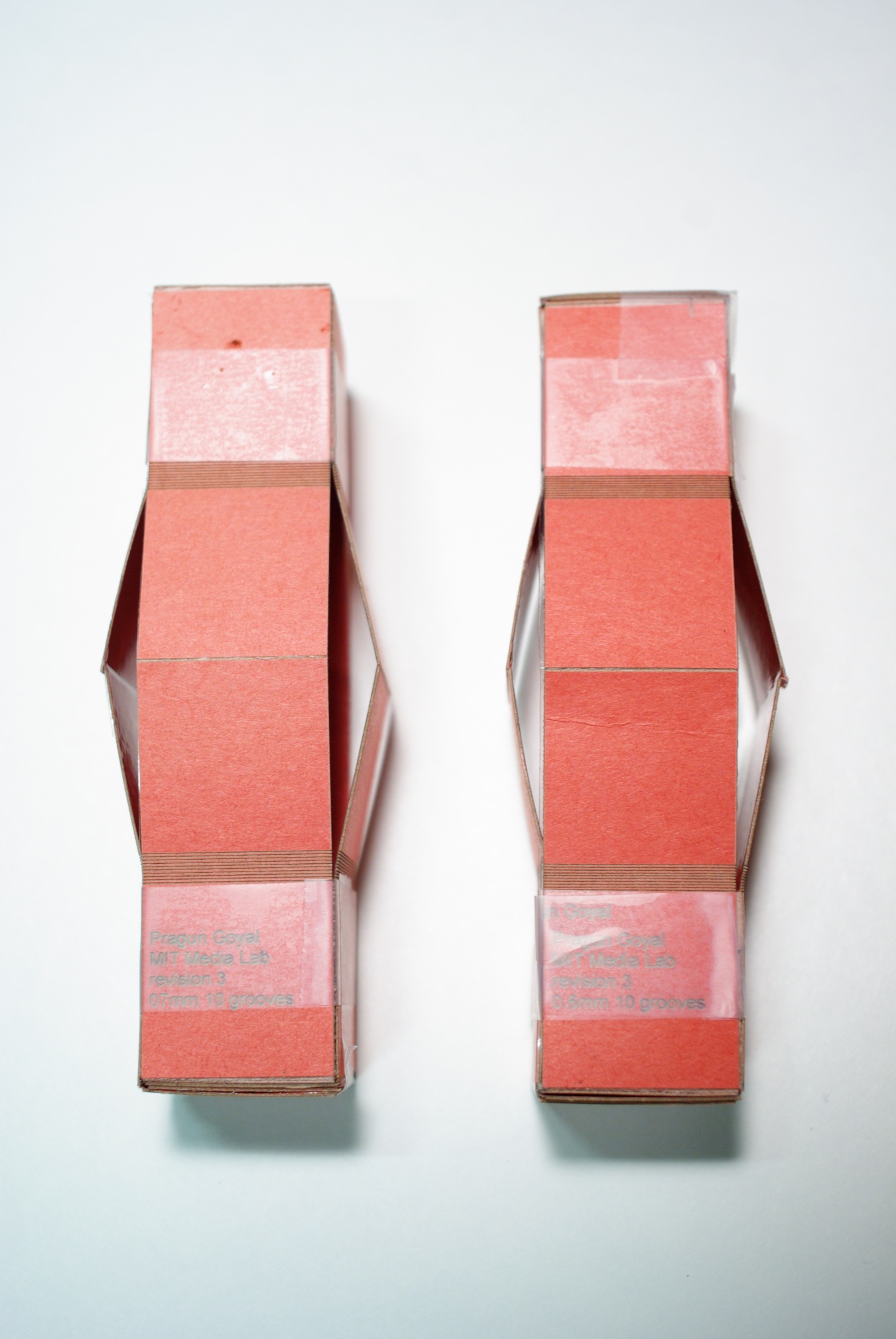
Revision3
Some problems/observations from revision3
-CorelDraw, has been having some problems interpreting dimensions from svg files generated by svgwrite
-As I haven't made any changes to the design, all issues from revision2 still remain to be solved. However, I'm hoping that the pythonic approach to generate design files would help me quickly iterate over parameters.
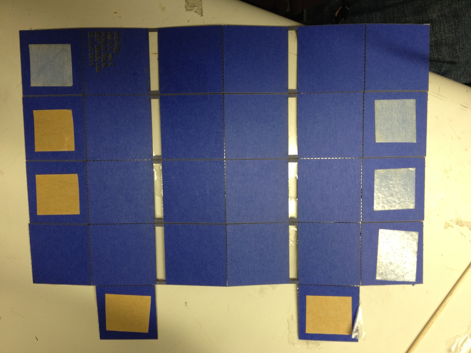
Revision4: Elasticity control cuts
Revision4
- I was able to figure out how to scale svgs generated by my python code for coreldraw. It was just about scaling the dimensions with a ratio.
- The effective length of the torsion springs formed at the hinges was controlled by removing a large part of the cardboard from the hinge.
- Rev4, unfortunately was never completely assembled, owing to the following problems.
- Creases introduced by the lamination machine
- Scores made by reducing the output power of the laser cutter are not ideal for 90 degree folds. The lamination just pulls several layers of the cardboard with it, making the overall behaviour unpredictable.
Revision 5: Elasticity control + Dash cuts == Sheer Awesomeness!
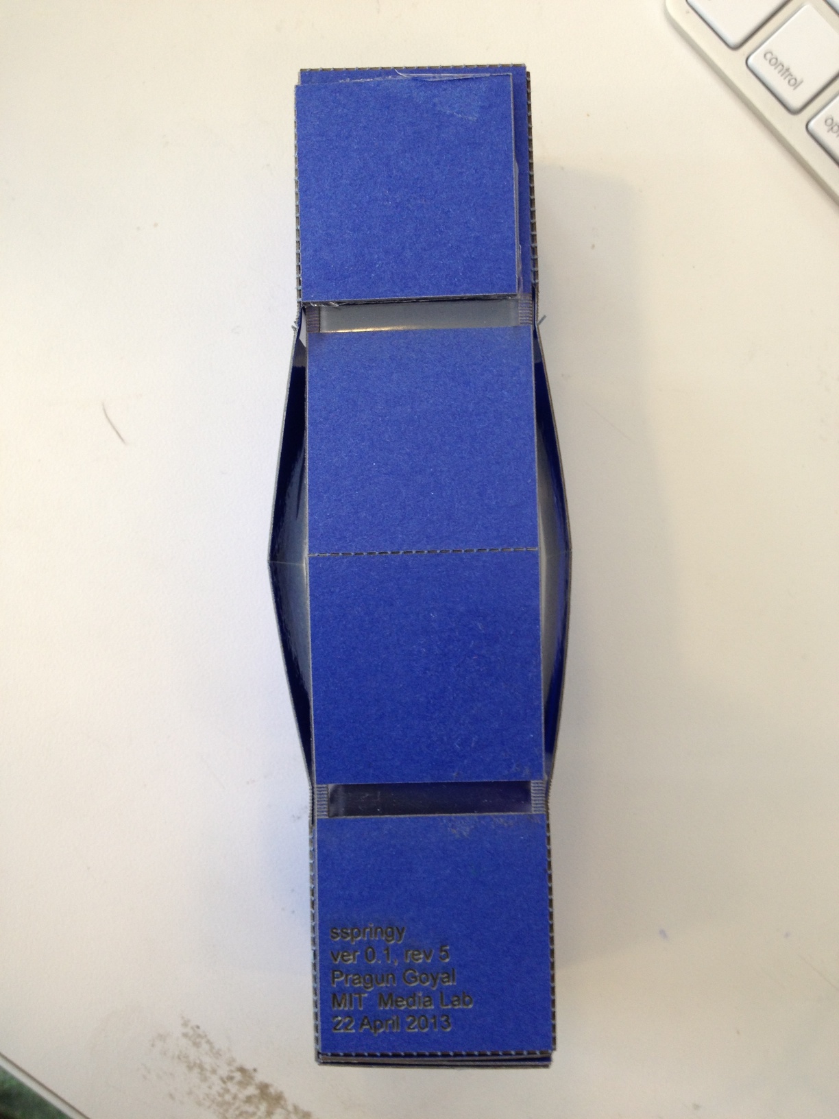
Revision5
- The elasticity control cuts work like a charm!
- The natural period of oscillation is still a little to high for nice playability.
Revision 6: Excellent playability!
Revision5
- The number of score lines for top and bottom hinges was increased to 20 from 10. To reduce spring coefficient.
- The fold cut for the top and bottom side flap is off by the thickness of the material. Inducing some unpredictable stress on the joints as they are assembled.
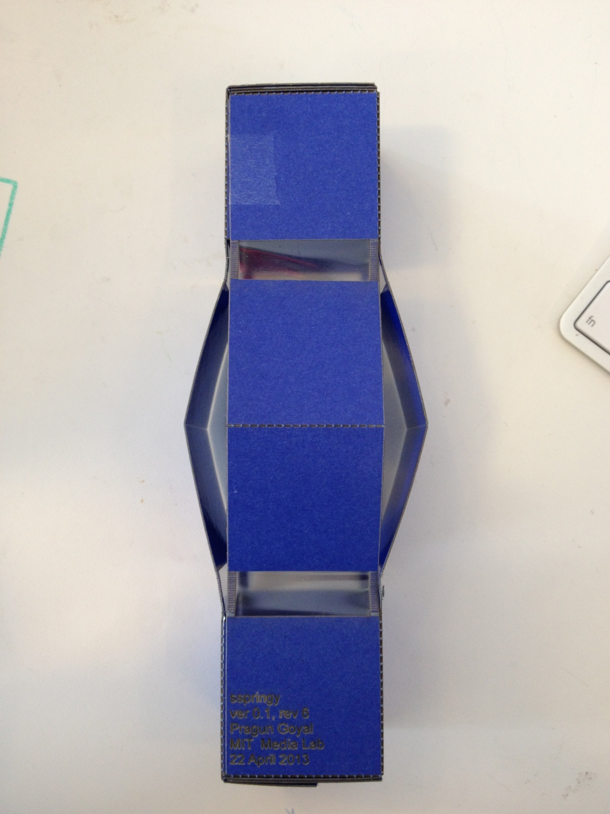
Revision 6: Excellent playability!
Revision6
- The number of score lines for top and bottom hinges was increased to 20 from 10. To reduce spring coefficient.
- The fold cut for the top and bottom side flap is off by the thickness of the material. Inducing some unpredictable stress on the joints as they are assembled.
- The flaps imbalance the weight, and cause the spring to at an angle to the vertical
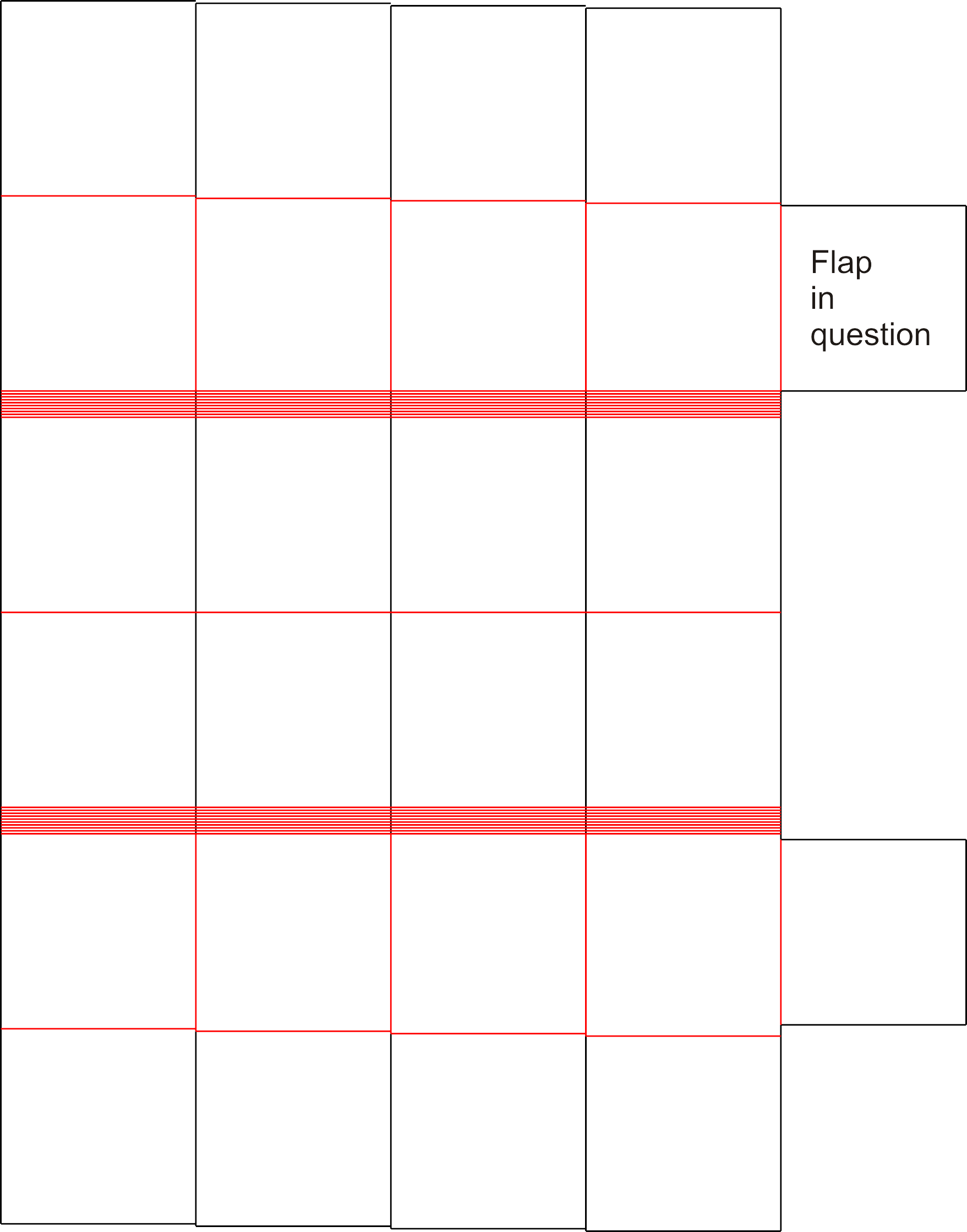
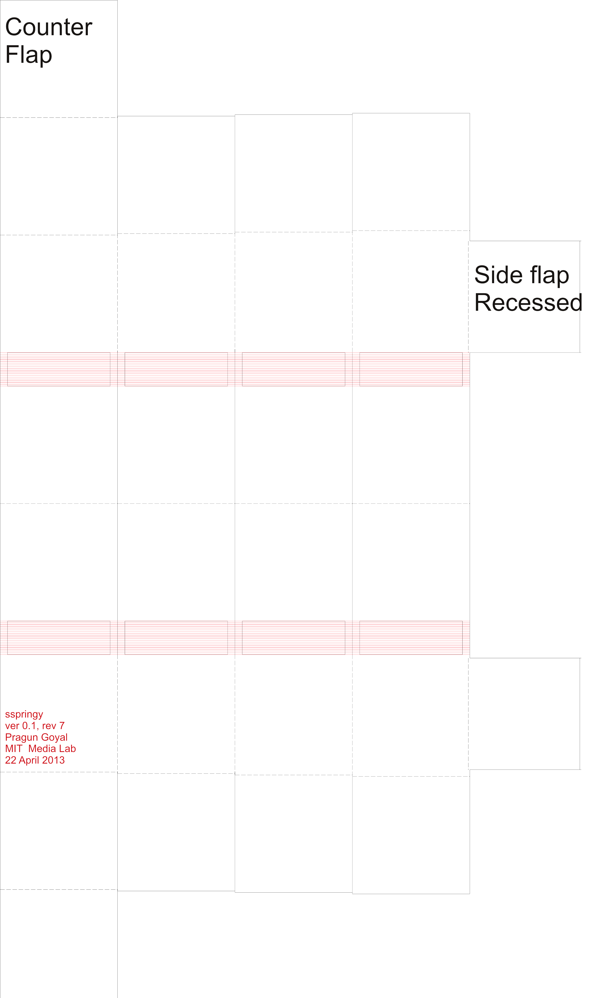
Revision 7: Perfect foldability!
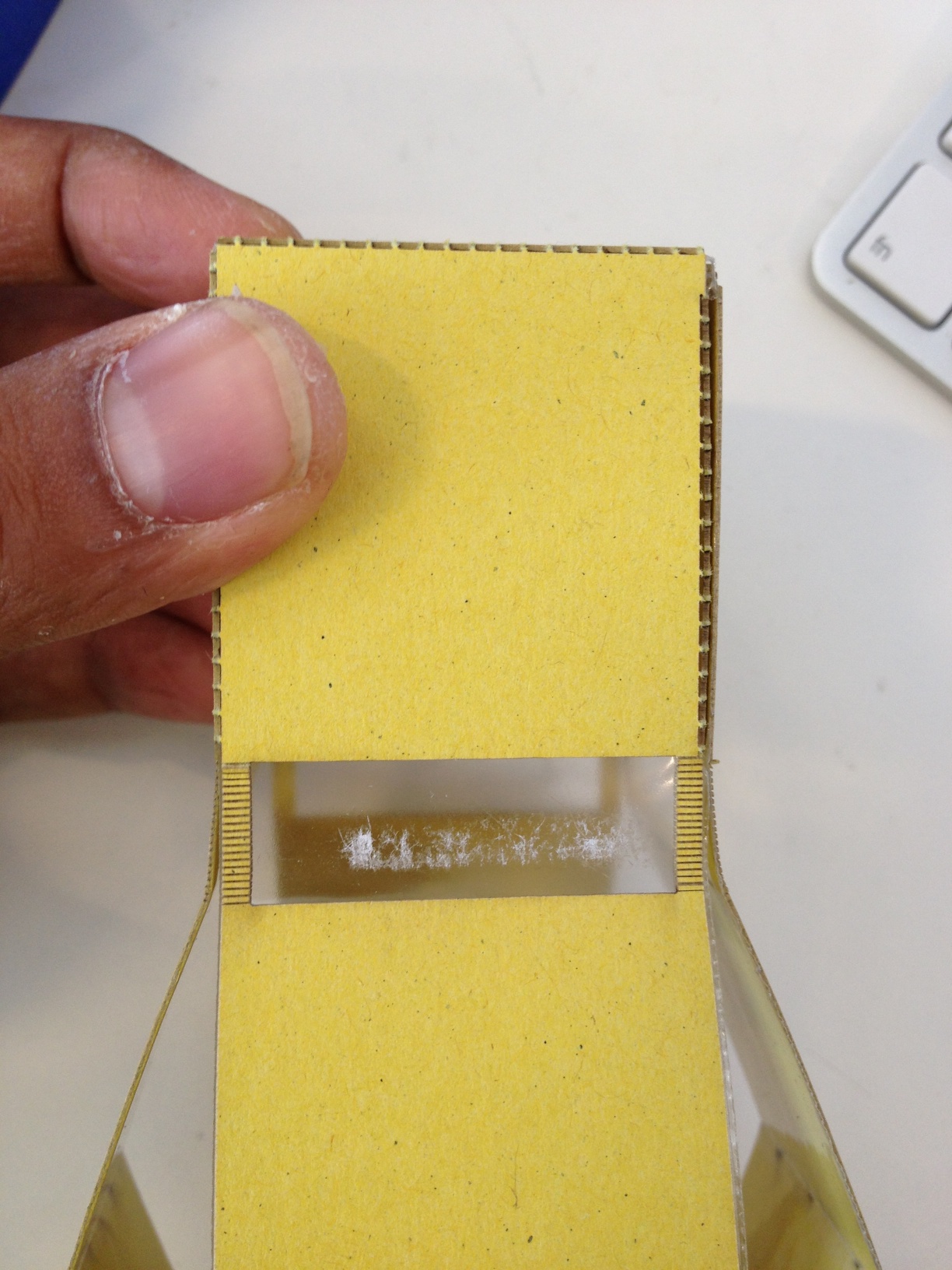
Revision7
- The fold cut for the flap was recessed by the material thickness (0.5mm) for excellent foldability
- An extra flap was added to counterbalance the weight of the side flap
- The fold cut for the top and bottom side flap is off by the thickness of the material. Inducing some unpredictable stress on the joints as they are assembled.
- The lamination process is made more failure proof
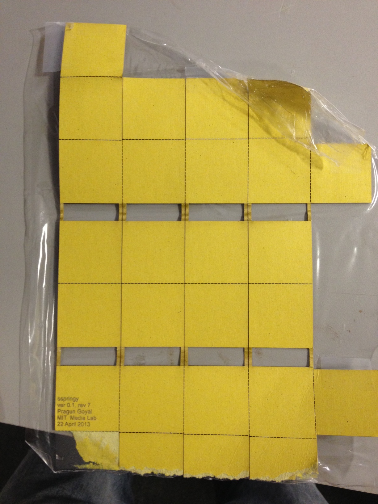
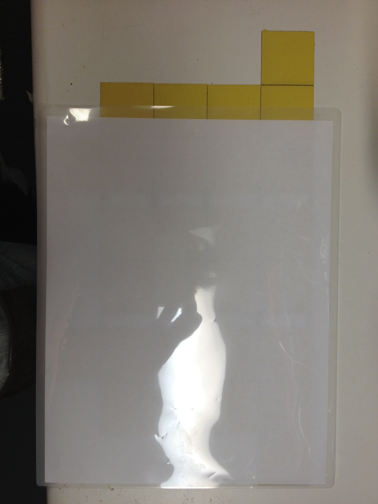
Both sides of laminating sheets are used to save the sticky side of one sheet from sticking to laminating rollers. A sheet of paper is put under the top lamination layer to keep it away from cardboard.
- The joints are made using thin double sided tape. Works like magic!
Both sides of laminating sheets are used to save the sticky side of one sheet from sticking to laminating rollers. A sheet of paper is put under the top lamination layer to keep it away from cardboard.
- Changed name to feee!, on the bright suggestion of a friend
- Two feee!s are joined in a vertical configuration. The springyness of the lower fee is calculated to give almost the same fundamental frequency as the top one when loaded with the top one.
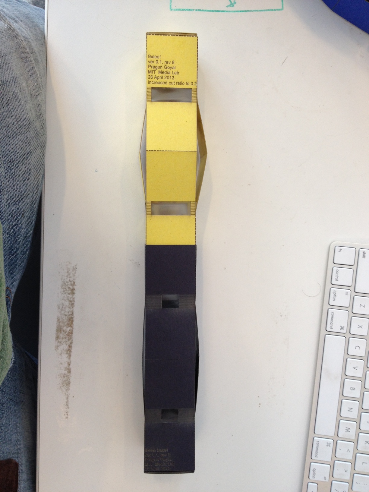
Both sides of laminating sheets are used to save the sticky side of one sheet from sticking to laminating rollers. A sheet of paper is put under the top lamination layer to keep it away from cardboard.
- Just for fun, I wanted to see how does it look when faces are etched on a fee.
- The materail I chose (unfortunately) has a different density and bendability. Resulting in poor playability.
- But, just for archival purposes. Here's what it looks like
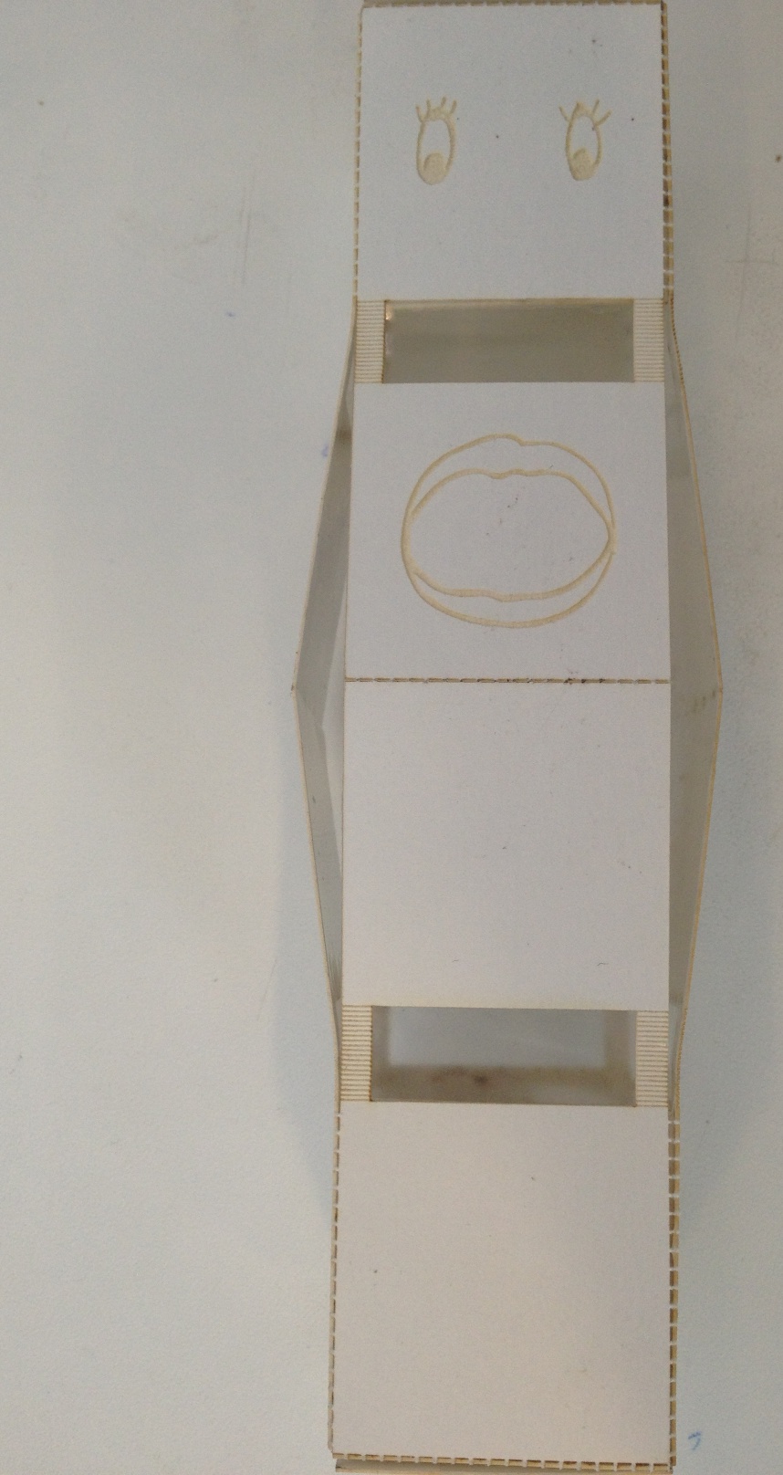
Both sides of laminating sheets are used to save the sticky side of one sheet from sticking to laminating rollers. A sheet of paper is put under the top lamination layer to keep it away from cardboard.
New Python library
- Abstracted out a lot of boilerplate to allow for more easy experimentation.
- Check it out here
Vibration TestingI finally started testing the springs on a little subwoofer I found. I just hooked up the subwoofer to a frequency generator :).