Build a Paramecium - Arduino Interface
In the experimental portion of this week, we designed a playground for paramecia and control their movement with the phenomenon of galvanotaxis. We began by modifying a vector drawing using CoralDraw and then rastering it out of acrylic using a lasercutter.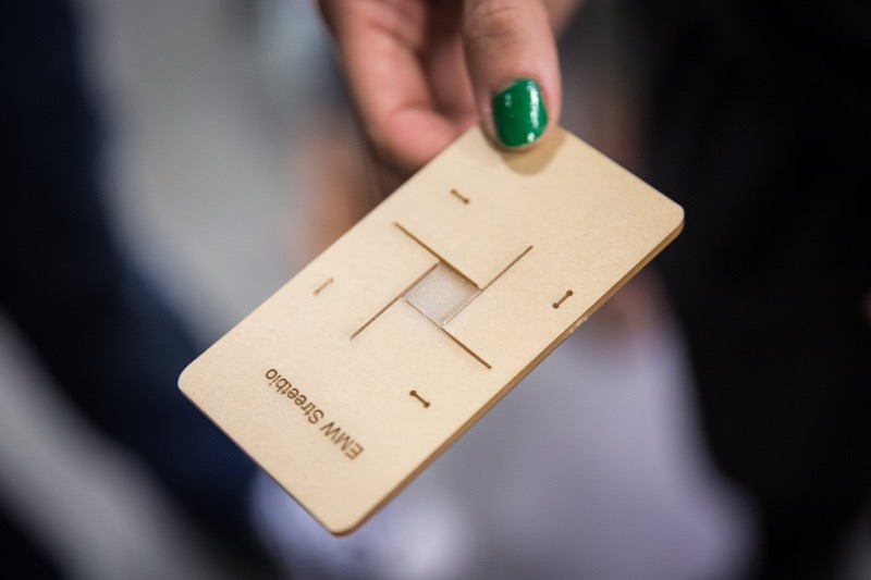 Next, we set up the experiment to measure how fast the paramecia will
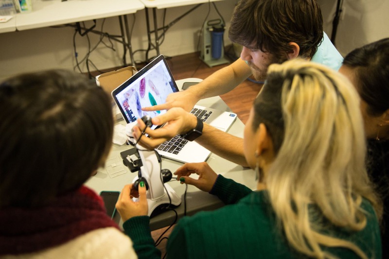
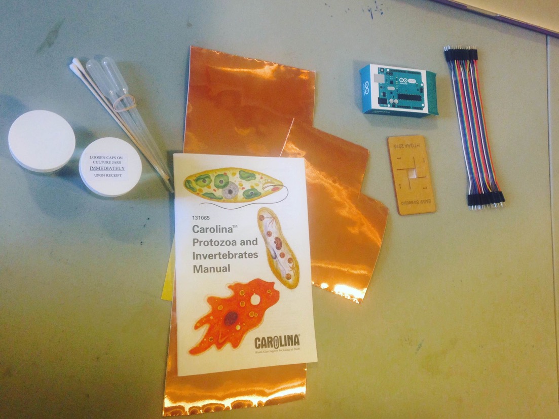
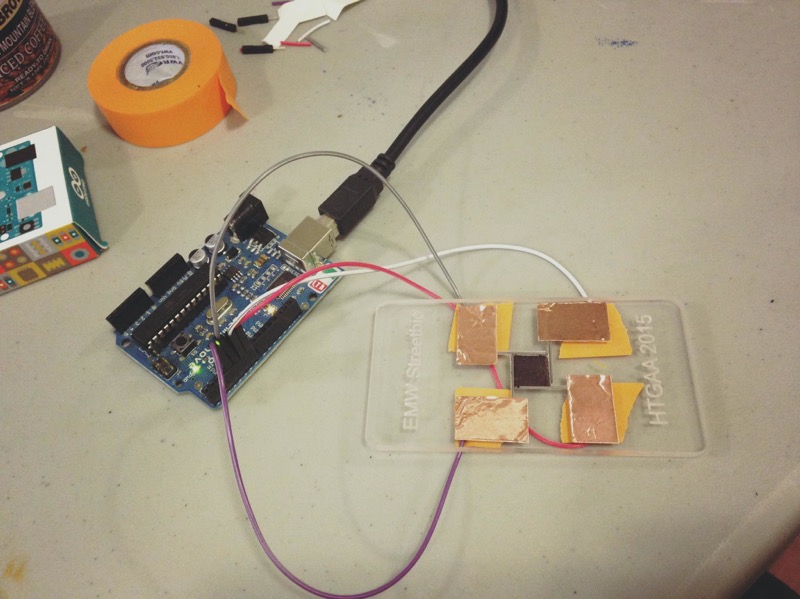
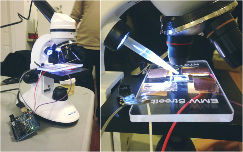
The set up involves: Paramecia from Carolina, copper tape, pencil leads, pippeters, arduino and our lasercut device. The assembled playground with electrodes were then connected to arduino. Finally, we placed our assembled device under a microscrope and pippetted the paramecia onto the center opening.
Explore bioreactor design elements
Problem 1: Design considerations for electrical stimulation systems
Below appears an oscilloscope reading for a stimulus waveform from commercial stimulator. When a bioreactor is attached (pink), the stimulus waveform (blue) is no longer faithfully applied.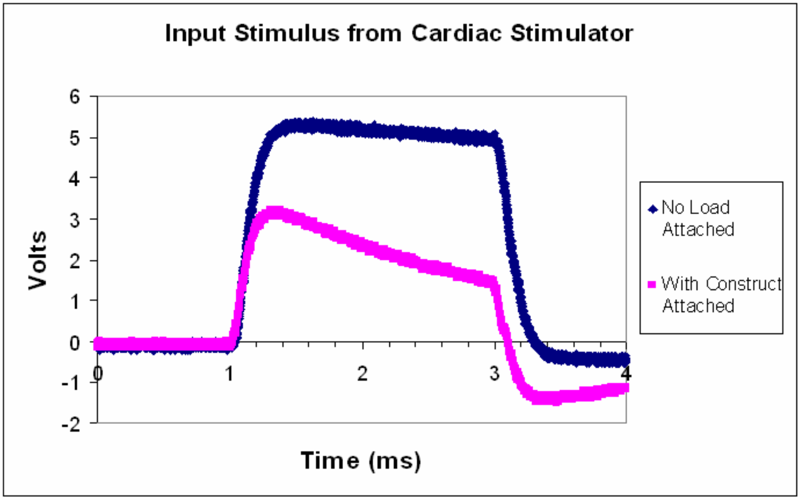
a) The stimulus waveform is approximately that of a square pulse of 5V amplitude. Describe what happens to the stimulus waveform with the bioreactor attached.
As noted we can see that when the bioreactor is attached, the waveform gets distorted and is not applied correctly to the load. In detail, upon attachment the stimulus no longer reaches the desired 5V, but maxes out at 3V and drops with a significant slope through the stimulation time. Moreover, when the pulse stops, there is a drift towards a negative voltage before the bioreactor's voltage recovers back to zero.
b) Assuming there is a single impedance value for a single bioreactor can you think of an explanation for why the stimulus waveform might be distorted when connected to the load?
The most reasonable explanation is due to current limitations of the stimulator. By Ohm's law, for a certain impedance we need a proportional amount of current to reach the desired voltage levels. The maximum voltage of the applied field is Im*Z, where Im is the maximum current that can go through the stimulator and Z the impedance of the bioreactor.
c) How might you expect the pink waveform to change if several of the same bioreactors were to be attached in parallel to this stimulator?
Having many stimulation chambers connected in parallel would degrade even more the electrical field applied to the bioreactor, as the current needed is adding up for each separate bioreactor. Rsum≪Rtot
d) What recommendation for modifying the stimulator would you make to solve this problem?
To have control over the applied field, you can either reduce the amount of current needed to reach the desired amplitude, by making the stimulus amplitude lower, or lessen the resistance of your bioreactor (e.g. shortening the distance of the electrodes) or, lastly, increase the available current by a higher current rating stimulator or an operational amplifier with high current gain.
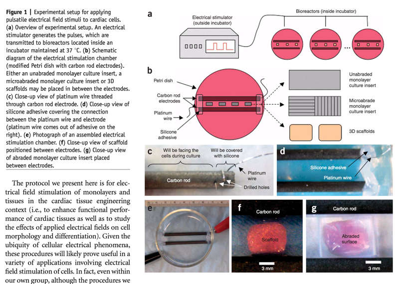
Diagram of Electrical stimulation systems for cardiac tissue engineering (Nature):
Problem 2: Morphological changes associated with electrical stimulation
Below appears Human adipose derived stem cells (hASCs) which were exposed to direct-current electrical stimulation for a period of 4 hours (from Tandon et al IEEE 2009).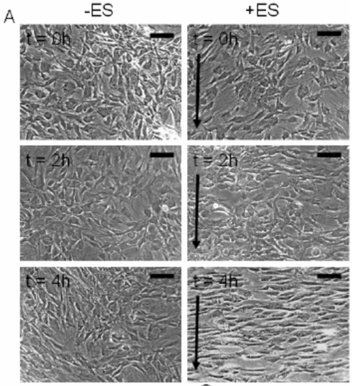
a) Using the above images, measure and graph (1) cell length and (2) orientation angle of cells at t=0, 2 and 4 h (use any software you like, I recommend image J software available at http://imagej.nih.gov/ij/). Scale bar corresponds to 200 um and arrows delineate direction of the electric field.
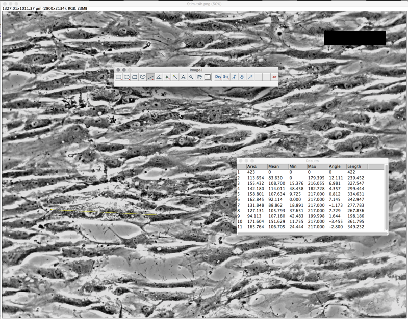
To use Image J (FIJI), open cell image, change threshold color
t=0H :: Cell Length = 215.22um ; Orientation angle = -5.57 degrees
t=2H :: Cell Length = 225.01um ; Orientation angle = -4.32 degrees
t=4H :: Cell Length = 299.89um; Orientation angle = 3.34 degrees
b) Describe the method used to identify cells (and include image captures at various stages of application of your method). State any limitations of your method, and any potential workarounds should you be able to change the experimental setup.
As shown below, we took the average of 10 cells in each image (t=0, t=2, t=4) using the Image J software.
c) Given the role of mesenchymal stem cells in wound healing, state any conclusions you may draw from your above analysis. What other results would you like to see in order to support this conclusion?
Problem 3: Design considerations for perfusion bioreactors
a) Paraphrase in plain English the worked example on pp 1191-93 in the Ratner Biomaterials chapter. State the assumptions and approximations regarding void volume, fluid velocity, channel geometry. How might you expect these parameters to change over time during bioreactor cultivation of stem cells towards bone tissue?
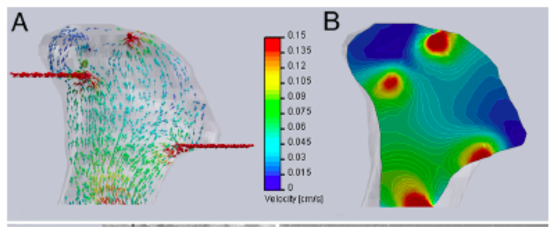
b) Now, examine the below computational models of medium flow through anatomically precise TMJ bone constructs during bioreactor cultivation(from Grayson et al 2009). (A) Color-coded velocity vectors indicate the magnitude and direction of flow through the entire construct based on experimentally measured parameters. (B) Construct is digitally sectioned, and the color-coded contours are used to indicate the magnitude of flow in the inner regions.