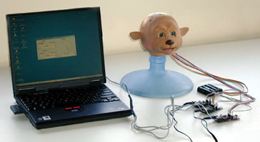
Robotic F.A.C.E.:Facial Alerting in a Communication EnvironmentMark Newman and Stefan Marti  GoalThe goal of this project was to create a head that can be used to display information. The face can be a very powerful method of conveying information, and a robotic head can serve as a very useful indicator. This project is meant to provide computer programs the benefit of using a physical object in the form of a face as a means of user interaction in addition to standard outputs such as a monitor or speakers. Currently, the head is being used with the ListenIn project, but it should be useful for many other applications.
Yano ToyThe main focus of this project had to do with creating an easy method for controlling the head from a computer. We did not want to spend time designing and building our own robot. Instead, we decided to use the head of children’s toy Yano, designed as an interactive storyteller. This toy head suited the needs of our project well because of its particularly expressive face.
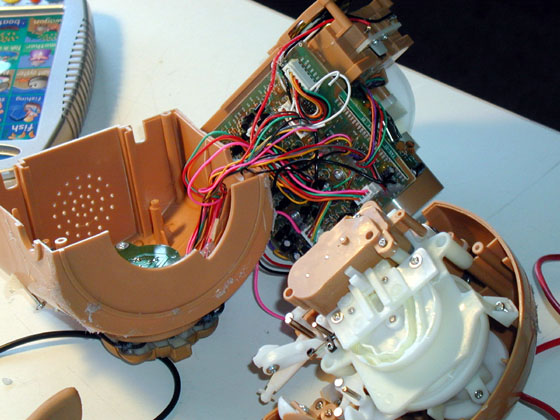
Mechanical HardwareAll the moving parts for this project are contained entirely within the head. They are all part of the original toy. Taking Apart YanoIn our project, we only used the head of the toy, but out of the box Yano’s head sits on top of a complete body. Most of the body, however, is devoted to the toy’s control circuits, “story cartridge” reader and an infrared receiver, none of which would be useful for this project. Still, it was necessary to take apart the toy’s body in order to gain access to its head. The body was not used after it was disconnected from the head.
In order to understand how to control the head, it had to be taken apart and put back together several times. To allow for this, the fur covering normally glued to the head was removed and set aside. Although it is possible to reattach the fur, the general consensus is that the head is more appealing bald than covered. Luckily the rubber that makes up the face is easily snapped on and off the five contact points that control its movement, allowing for repeat disassemblies. After the face and fur are removed, the entire head can be taken apart with a single screwdriver.
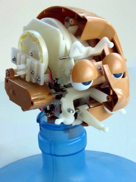
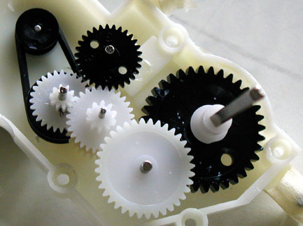
The HeadAll movement in the head is driven by three DC motors. Each motor is built into the head and has its own gear reduction box also in the head. All of the motors are driven using a six volt pulse width modulated signal. Originally, the toy would have used an unmodulated six volts. It is important to know the position of each motor both to achieve the desired movement and to prevent the head from damaging itself. To achieve this, the toy has two types of internal sensors. Two of the motors sense their positions using end switches. These are simple mechanical switches located at the ends of travel for the motors’ respective mechanisms. Once the mechanism arrives at a switch, it pushes two contacts together closing a circuit.
The remaining motor has a more sophisticated method of determining its position. Two of the gears involved in reducing the motor output have holes in them. Two infrared LEDs shine light on these gears, with an infrared detector for each on the other side. The detectors are only able to receive IR light when the holes are directly between an LED and its detector. In this way, it is possible to know how many revolutions the gears have made and thus the position of the motor.
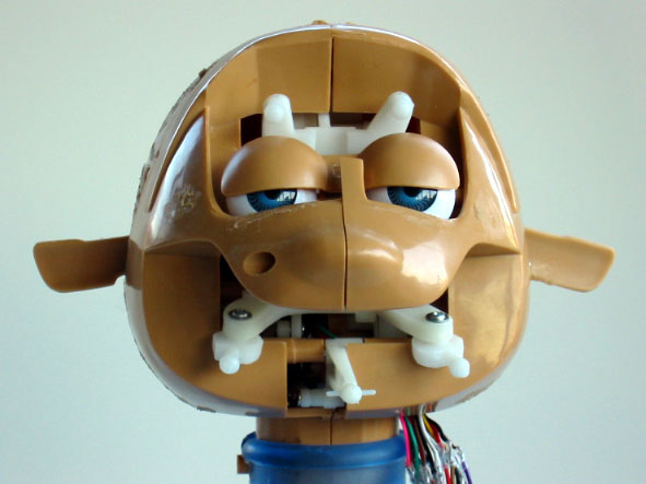
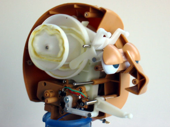
Degrees of FreedomThe Yano head has three degrees of freedom controlling five facial features. The mouth and cheeks each have their own dedicated motor which can manipulate them up and down. These are the two motors with end switches. The mouth motor triggers its end switches when the mouth is fully open and fully closed. The cheeks, which could also be considered the corners of the mouth, can move very high up in the face but not too far down.
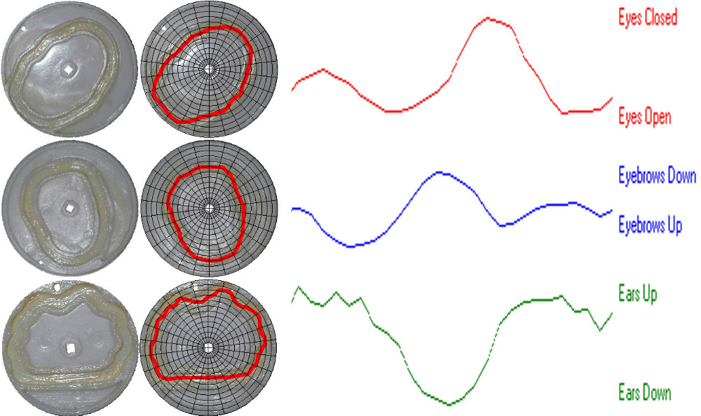
The other three facial features are the ears, the eyebrows and the eyelids, and are all controlled by a single motor. The motor turns a large shaft that runs across the inside of the head from ear to ear and turns three wheels. Each of these wheels has a track that runs along the side of it with a varying radius. As one of four pins follows its track, it is moved in and out, manipulating the face. In this way, all three facial features are coupled and can be moved in a continuous loop.
Control HardwareAlthough most of the interior of the toy’s body was taken up by circuit boards, these could not be used. In order to take control over the head, it was necessary to design an entirely new method of control. Hardware LayoutTo make the head work properly, a computer must have control over all three motors simultaneously. In addition, it is important to be constantly monitoring all four end switches and both IR detectors. To accomplish these tasks, the motors are dealt with individually along with their sensors. Each of the three motor and sensor sets are driven using a PIC microprocessor on an iRX board. The iRX boards each connect only to their motor and sensors in the head. For instance, the mouth is driven by the same iRX board that monitors the two mouth end switches. The computer communicates to the iRX boards using the computer’s serial out. The signal from the computer is split and sent to all three boards.
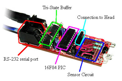
iRX BoardsThe iRX board is a small kit that provides everything needed to use a PIC microprocessor. It includes an RS-232 serial port, an oscillator needed to run the PIC, a status LED, IR LED and receptor, and a voltage regulator so that any standard 9V battery (or equivalent power supply) can be used to power the PIC. The iRX board also has a small prototyping area for additional circuitry if desired. For this project, the iRX board ended up being exactly want we needed to connect the computer to the head.
Sensor CircuitsIn order for the sensors to be usable to the PIC microprocessors, there must be a small amount of circuitry between the head and the PIC. Fortunately, there is enough space to place the needed circuits directly on the iRX boards. The circuits are different for the two types of sensors, but both are very simple. Serial CableThe easiest way for the computer to communicate to the iRX boards is to send the same signal to all of them. This was done by splicing three cables on one end with one cable on the other. In this way, the computer can send signals as if it were only communicating to one iRX board, and each board can receive as if it were the only board receiving It is not as simple, however, for the iRX boards to send signals back to the computer. Unfortunately, connecting the transmit lines of the three boards causes them to interfere with each other. To prevent this from happening, all but one of the transmit lines must have high impedance to allow for transmission. A tri-state buffer can allow normal digital signals to be transmitted, but also may be in a high impedance state. Adding a tri-state buffer to each iRX board allows them to transmit back to the computer as long as only one board is communicating at a time. PIC SoftwareThe PIC microprocessors, in the iRX boards, take high level commands from the computer regarding motor position and carry them out using sensor information. The software for the PICs was compiled from code written in C. The PICs used in this project were all 10 MHz versions of the 16F84. Here is the code for the face iRX board, for the cheeks iRX board, and the mouth iRX board (the latter two are very similar). PIC I/OThe mouth and cheeks are driven by virtually the same PIC program since they have corresponding hardware. It is very easy to get the mouth and cheeks to go to their end positions since these are where the end switches get triggered. It is significantly more difficult to get the motor to go to an intermediate location. To achieve this, the PIC measures the time it takes the motor to travel from one extreme to the other when its program is first run. Once the travel time is known, the PIC is able to attain intermediate locations by turning on the motor for the appropriate fraction of the total travel time. The motor controlling the rest of the face has a completely different PIC program. One of the IR detectors can only be triggered at one position in the rotation. When the program is first run, the PIC rotates the motor until this position is found so that the wheel’s absolute location is known. From there, all movements are made by counting the number of times the fast IR detector is triggered. The fast IR detector is triggered 26 times every revolution of the wheel. To decrease any error, the PIC “zeros” itself every time the slow IR detector is triggered. Computer – PIC CommunicationIt is very important for the PICs to know which one the computer is talking to because all three receive the same signal. It is also important for the PICs to not attempt to transmit at the same time. Because of this, the computer and the PICs both adhere to a strict communication protocol.
The protocol consists of three bytes, two from the computer, and one in response. The first byte contains an identifier that specifies to which PIC the second byte is directed. This is the same PIC that will send the response. The first byte also contains information telling the PIC at what speed its motor should be run. The second byte differs depending on what facial feature or features the target PIC controls. If it is one of the mouth or cheek PICs, the second byte can take one of three formats. These will tell the PIC to do nothing and just send a response, tell the PIC to go to one of the end switches, or tell the PIC to move to a specified intermediate location. The third PIC has two possible messages; do nothing and just send a response or go to a specified location rotating either clockwise or counterclockwise. The response byte is very simple. It merely tells the computer if the motor associated with the PIC is currently moving or not. It also can tell the computer the position of the motor in the case where the motor is tracked by LEDs. If the PIC is indeed busy with moving its motor, than a command by the computer to take a different action will be ignored by the mouth and cheek PICs. A PIC that returns a status of ready will always be able to accept a command. VB SoftwareVisual Basic allows for easy access to the serial port as well as makes creating user interfaces very easy. For these reasons it was used to write the computer programs. Direct ControlTo allow for maximum access over all of the head functions, this program gives the user direct control over the messages sent to the PICs. For the ears, eyebrows and eyelids, it has a representation of the motor position, showing the current location inside the head. It allows the user to click on this indicator to set the location that the motor should go to. The mouth and cheeks each have two buttons that will send the appropriate motor to the corresponding end position. They both also have a slider which can be used to tell the motor to go to an intermediate position. All three motors have sliders that set their speed.
Static and Dynamic EmotionsSome of the uses for this project might call for the head to display recognizable emotions. The intention was to create nine or ten hardcoded face configurations and then move between them as necessary. The GUI allowed the user to choose these emotions via specific buttons.
However, this approach ended up not working out for a few reasons having to do with physical constraints deriving from the original toy. Ideally, the head would have behaved in a way similar to Cynthia Breazeal’s robot Kismet. Due to the similarity of the affect space used for Kismet and the needs of this project, the algorithm for generating facial emotions was based heavily on Dr. Breazeal’s work. Unfortunately, because the head was developed to be used as a toy for young children, it was not able to satisfactorily achieve several of the needed basis poses necessary to complete Kismet’s affect space. In addition, the fact that the movement of the ears, eyebrows and eyelids are tied together prevents any type of smooth transitions between facial expressions.
Some of the facial expressions work better than others ListenInThe head was, however, successfully used for a different purpose. ListenIn is a system developed by Gerardo Vallejo that allows users to monitor the activities taking place at a remote location. To help preserve the privacy of any persons at the monitored site, ListenIn relies only on sound from the site and garbles sound clips it determines contain speech before playing them for the user. But if further privacy is desired, the entire user interface may be replaced by a robotic head.
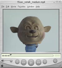
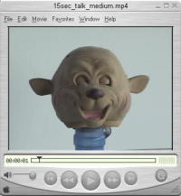
The head is set up to display only two types of responses. The head can respond to the detection of speech and the head can respond to the detection of sound not determined to contain speech. Under normal silent conditions at the monitored site, the head is asleep and not moving at all. When ListenIn detects a sound event at the monitored site, the ListenIn server sends the user’s client a message indicating that an event has occurred. This message causes the head to suddenly wake up, moving the ears, eyebrows and eyelids at full speed. As time passes after the event message is received, the head begins to slow down its movement and spends more time with its eye’s closed. If the ListenIn server indicates that speech was detected, the mouth talks in addition to the other movement. The mouth moves fast at first and as it slows down, does not open as widely. Eventually, the mouth closes fully and the head falls back asleep.
Update: Check out Super Yano, our Yano's big brother! Very impressive!
Send me some comments! Copyright © 1997-2004 by Stefan Marti, Mark Newman, and MIT Media Lab. All rights reserved |