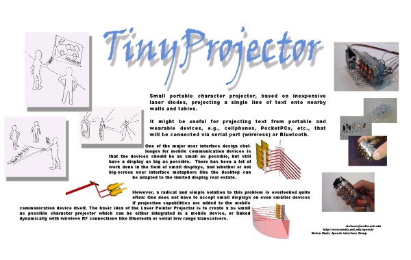
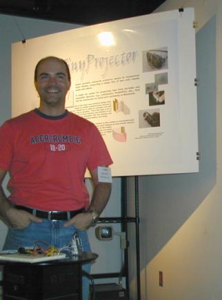
TinyProjector
Stefan Marti, MIT Media Lab
October 2000 – May 2002
Summary
The biggest challenge for designers of mobile communication devices is presenting large amounts of information on very small displays. As the form factor of these devices continues to get smaller and our demand for mobile information continues to grow, the task only gets more difficult.
The solution to this dilemma cannot simply consist of adapting design principles, like the desktop metaphor, to fit the limited real estate. Adding projection capabilities to the mobile device itself might pose a possible solution to this problem.
The basic idea of TinyProjector is to create the smallest possible character projector that can be either integrated into mobile device, or linked dynamically with wireless RF connections like serial low range transceivers.
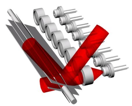
After extensive research, and having explored many non-viable alternatives, a completely new prototype (number 9) was designed and built, making intensive use of 3D modeling CAD software and the 3D printer.
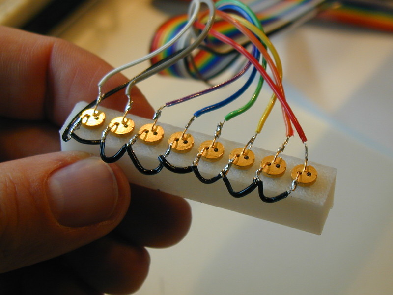
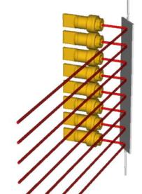
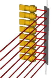
The overall design is radically simplified and miniaturized. Compared to all the earlier versions, which used laser diodes salvaged from cheap key chain laser pointers, the current prototype has smaller low-cost low-output laser diodes that allow for just one row of eight lasers instead of two interlinked rows of four lasers, making cumbersome primary deflection mirrors obsolete.
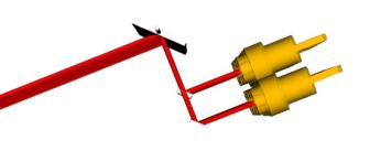
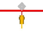
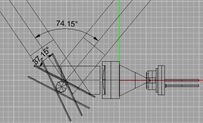
A micro motor with a single swiveling servo arm, making a continuous full 360-degree rotation, drives the deflection mirror, resulting in a 38-degree left-right sweep. This leads to an unusually high overall laser projection angle of 104 degrees.
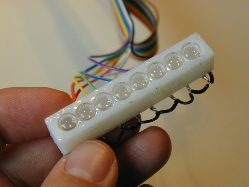
All body parts of the prototype, including the critical lens assembly and mirror holder, were designed completely in CAD software, and then 3D printed in ABS plastic.
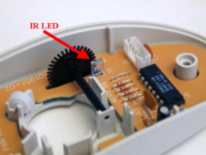
The system is now closed loop: an IR LED/photodiode combination signals the PIC chip when the mirror is at its origin, which enables a precise overlapping of the laser pulse sequences.
Compared to the earlier prototypes, a PIC chip with more memory (and EEPROM) is used in the current prototype, which allows storing character templates for the complete alphabet as well as some special characters.
A two-way serial port connection with both Palm PDAs and Java enabled cellphones is demonstrated. From either device, arbitrary text can be sent to the projector and is displayed; in addition to that, preset text lines stored on the projector itself can be triggered from these devices.
The current prototype is capable of displaying 8 characters, each consisting of an 8x5 pixel matrix. (However, tests have shown that the horizontal resolution can be easily increased by at least factor 10, and the vertical distance between the laser beams could be reduced by factor 2. In such a configuration, the prototype could project two to three times more characters than the current prototype.)
Very important, the projection refresh rate of the third prototype is increased to about 25Hz, which is significantly higher than the earlier prototypes that had a refresh rate of only about 3Hz, and therefore had to rely on the effect of persistence of vision. The projection of the current prototype appears stable, easy to read, and—after intensive debugging and mechanical tuning—almost jitter free. However, the overall brightness of projection is lower than of the projectors based on persistence of vision, due to the increased refresh rate. Furthermore, the amount of vibration has increased, which is due to the higher RPM of the micro motor, together with the inherent inertia of the stainless steel mirror. Nevertheless, the primary goal of TinyProjector prototype 9 was to make the projection "usable" and readable. This goal has been met.
In order to document this work, an extensive lab notebook has been written, including several hundreds of pictures, scans, screenshots, and movies.
Prototypes
|
|
Features |
Problems |
|
|
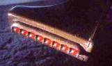
· 8 big key chain laser pointer laser diodes · Single row · Hold by single acrylic plate (laser cut) · Skyliner™ electronics · 8-faced mirror, continuously rotating |
· System not closed loop: synchronizing motor speed with laser pulses not possible · Mirror way too bulky for mobile use · Alignment of laser diodes virtually impossible, since the laser diode capsules are imprecise |
|
|
· 8 big laser diodes · Two parallel rows, interlaced · Hold by two parallel acrylic plates (laser cut) · 8 secondary mirrors for laser beam alignment, mounted on U wires · Left-right sweeping mirror, driven by commercial RC servo, controlled by PWM signal created by PIC · Custom electronics (including small PIC controller 16F84) · Very high brightness and visibility of projection, even on black backgrounds |
· Relies on persistence of vision principle, so only very low refresh rate (3Hz) · Relatively noisy · Still too big for mobile use |

|
|
Features |
Problems |
|
|
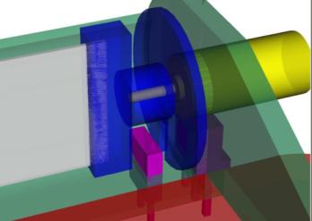
· 8 big laser diodes · Two parallel rows, interlaced · Hold by two parallel acrylic plates · 8 secondary mirrors for laser beam alignment · Custom electronics (16F84 PIC) · Add-on mirror assembly (3D printed) · Continuously rotating, two-faced mirror (single stainless steel strip, no continuous axle), held with 3D printed parts on each end · Driven by 6mm motor · Closed-loop system with IR LED and photodiode |
· Mirror not turning lightly enough: the stainless steel strip by itself was not rigid enough, because there was no continuous axle · Laser diodes not bright enough for the low duty cycle of 360-degrees continuously rotating mirror: with a projection angle of 60 degrees, only about 8% of the time the lasers are actually on |
|
|
· 8 smaller laser diodes (Lumex or Honeywell) · Mirror made of two strips of stainless steel and centered axle (all the way through) · Continuously rotating mirror · Belt driven via pulleys and by 6mm motor · Compact size (no secondary mirrors, motor is parallel to laser array) · Diodes mounted via their contact wires, for easy alignment |
· Gear box difficult to align: if belt tension too high, then friction too high; if tension too low, the belt jumps out of the pulleys easily · My laser diodes not bright enough for such low duty cycle of rotating mirror |

|
|
Features |
Problems |
|
· 8 Lumex laser diodes · Single row, very compact, very rugged · Diodes and lenses mounted directly on 3D printed holder |
· Holder not precise enough, due to limitations of 3D printing head · Alignment calibration not possible, and very much necessary! |
|
|
· Continuously rotating, very light going mirror assembly; virtually NO vibration! · Mirror made of single axle (centered) and 2 strips of stainless steel, very rigid · Direct driven by 6mm pager motor |
· My laser diodes not bright enough for such low duty cycle of rotating mirror |
|
|
Features |
Problems |
|
|
|
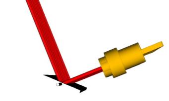
· Left-right sweeping mirror · Mounted on simple scotch tape hinge · Driven via one-arm crank (ABS) on a 6mm motor · Closed-loop system with IR LED and photodiode |
· Modest vibrations · With ABS crank arm very jittery projection trajectory of the laser beams |
|
|
|
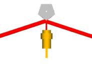
· Left-right sweeping mirror · Mounted on simple scotch tape hinge · Driven via one-arm crank (ABS) on a 11mm diameter motor · Very high refresh rate possible! |
· Noisy · Strong vibrations · Relatively big |
|
|
|
Features |
Problems |
|
|
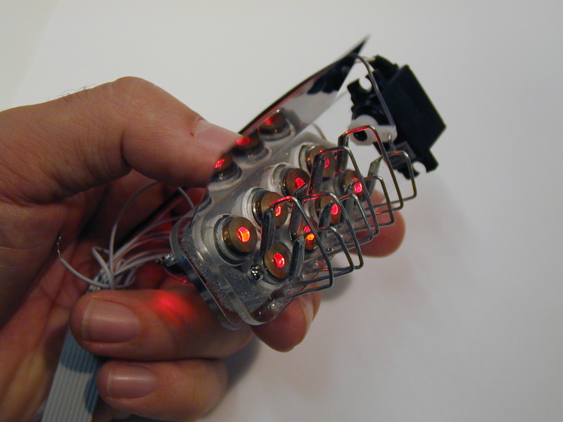
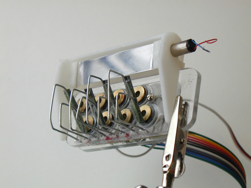
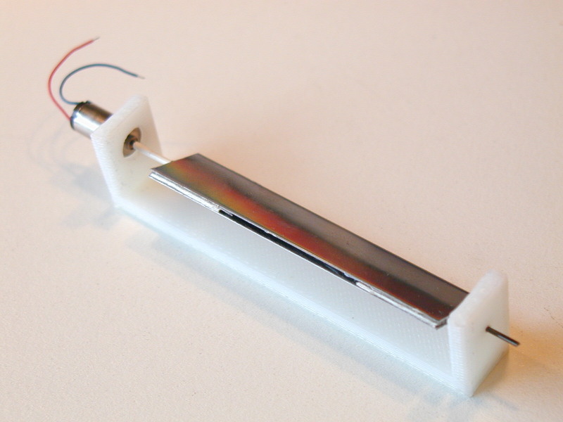
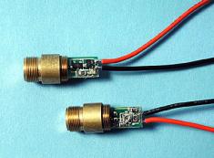
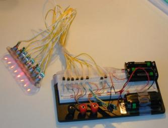
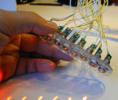
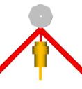
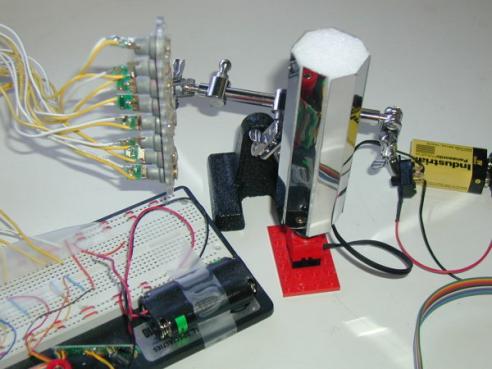
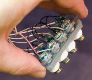
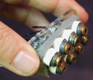
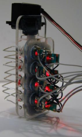
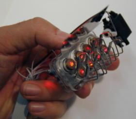
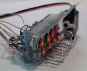
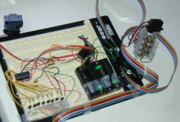
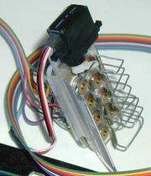
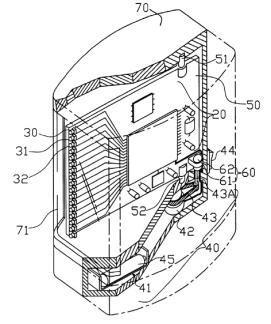
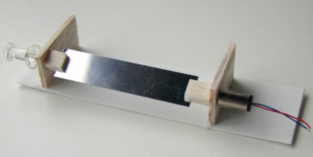
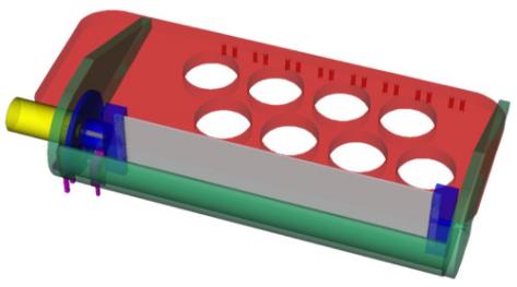
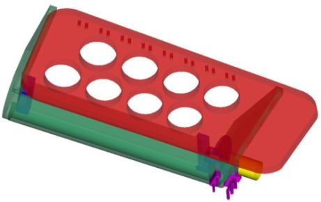
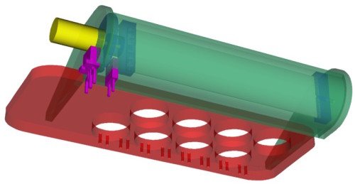
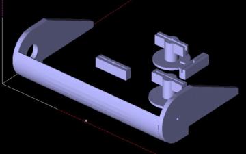
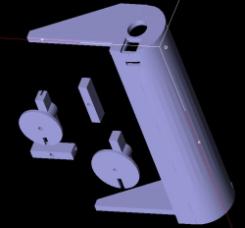
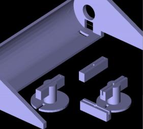
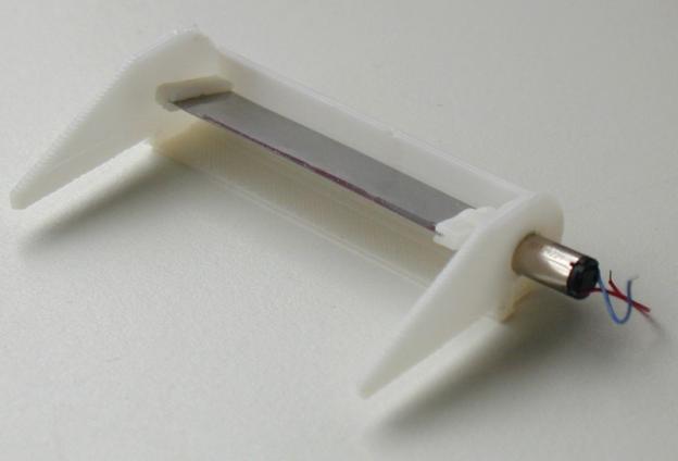
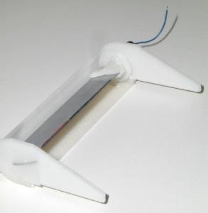
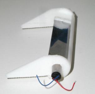
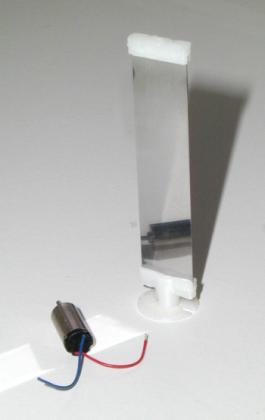
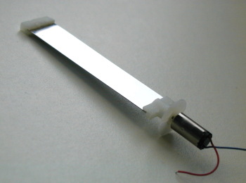
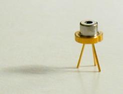
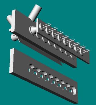
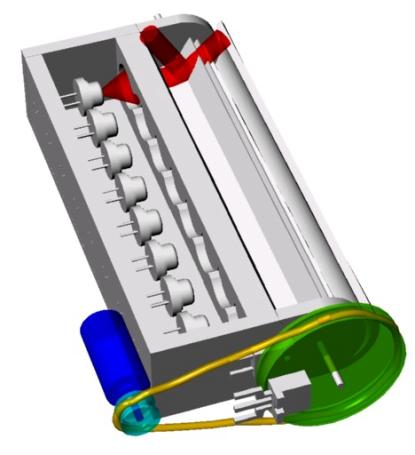
· 8 Lumex laser diodes · Single, compact row · Separately 3D printed holder for lenses and diodes · Diodes mounted with U shaped double wires · Sweeping mirror (single strip stainless steel), mounted on single axle at one edge of strip · Driven via one-arm crank (aluminum) and 6mm pager motor · Closed-loop system with IR LED and photodiode · Refresh rate 25Hz · Bigger PIC (16F877) with enough memory to display all characters · Serial connection · Can be connected to Palm Pilot™ or Java enabled cellphone |
· Fragile, since all laser mountings (double wires), as well as the motor crank, are mechanically exposed
|
|
|
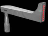
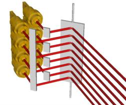
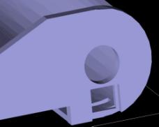
· Like prototype 9, but with complete housing, protecting the laser mountings and the motor crank
|
|

Original Proposal
Basic Idea
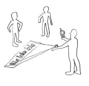
The basic idea is to build a small portable character projector, based on inexpensive laser diodes, that is able to project a single line of text onto nearby walls, tables, and other surfaces. This would be useful for projecting text from portable and wearable devices, e.g., cellphones, PocketPCs, etc., that are connected via serial port (wireless) or Bluetooth.
|
|
|
|
|
|
|
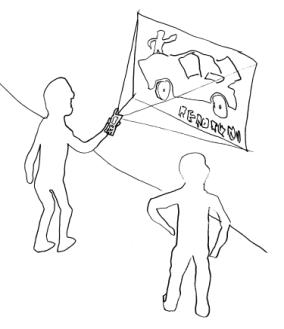
Figure 1: First design sketches for TinyProjector, developed in October 2000 for a MIT Media Lab class. It was conceived as the output module of an interface to an intelligent single-point remote control for all home appliances. The underlying metaphor is a "magic lamp" that is home of a genie. The projection would appear out of the top of an old oil lamp when the user rubs the lamp, symbolizing the friendly ghost that can control all home appliances. |
|
Motivation
One of the major user interface design challenges for mobile communication devices is that the devices should be as small as possible, but still have a display as big as possible. There has been a lot of work done in the field of small displays, and whether or not big-screen user interface metaphors like the desktop can be adapted to the limited display real estate.
One solution for the dilemma would be look-through devices like Invisio’s eCase (http://www.inviso.com/ecase.html). However, they are only one-person displays: only a single person can see the content.
It looks like another, radically simple solution to this problem, might have been mostly overlooked: One does not have to accept small displays on even smaller devices if projection capabilities are added to the mobile communication device itself. The basic idea of the TinyProjector is to create a as small as possible character projector which can be either integrated in a mobile device, or linked dynamically with wireless RF connections like Bluetooth or serial low range transceivers.
Realization
I suggest two steps for the realization:
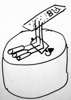
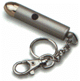
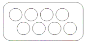
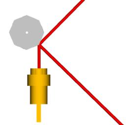
Step 1: Testing the idea by replacing the 8 LEDs of a Skyliner™ toy with 8 laser diodes of small key chain laser pointers.
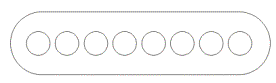
The Skyliner™ (http://www.theskyliner.com) is a little gadget, approximately the same shape as, and a bit larger than a New Year's noisemaker. It runs on two AAA batteries. There is a row of 8 red LEDs on the end. Three buttons located near the handle allows the user to change to any of 10 pre-set messages, or create up to three new ones. One holds the thing over the head and whirls it about by its handle, and messages, spelled out in red LEDs, appear “magically” in mid-air.
|
|
|
|
Figure 2: Skyliner™ toy |
|


By replacing the LEDs with laser diodes, and adding a turning mirror in front of the laser beams, the device should project the messages (pre-set or programmed), onto nearby walls or tabletops.
|
|
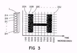
|
|
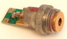
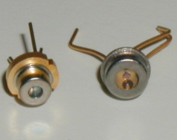
Figure 3: Key chain laser pointer (left), laser diodes (right) |
|
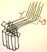
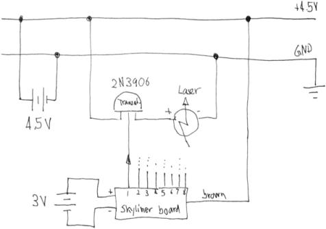
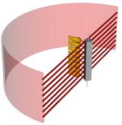
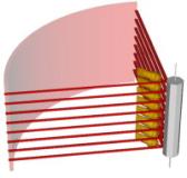
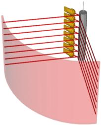
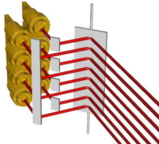
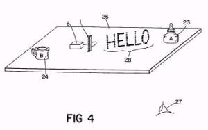
The laser pointers would be powered via a transistor and a separate 3V power source. A rotating mirror would project the laser beams (theoretically) 360 degrees onto the walls (Figure 4).
|
|
|
|
Figure 4: Array of eight laser pointer diodes, arranged in one row, and a rotating mirror with two surfaces. |
|
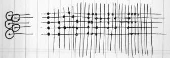
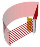
To make the projector more compact, an additional set of secondary mirrors would allow bringing the laser beams closer to each other (Figure 5).
|
|
|
|
Figure 5: Array of eight diodes, arranged in two rows, with secondary mirror. |
|
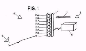
Step 2: Replace the Skyliner™ electronics with a PIC chip that drives the laser pointers directly.
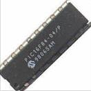
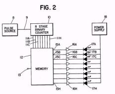
The PIC chip would receive the text to project as serial data, perhaps wirelessly from serial low range transceivers (Abacom, Linx) or Bluetooth chipset. The PIC needs at least one leg (input) per laser diode (8), and possibly other inputs for adjusting the scan frequency as well as synchronization of refresh rate with mirror rotation. Hopefully PICs like the 16F84 that can power the laser diodes directly (can provide enough current and voltage), making transistors obsolete.
- 16F84: 18 pin CPU with 68 bytes of RAM and 1024 words of on-chip EEPROM program memory, http://www.microchip.com/10/lit/pline/picmicro/families/16f8x/devices/16f84/
|
|
|
|
|
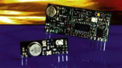
Figure 6: Abacom/Linx low range RF transmitter/receivers (left, middle), PIC chip 16F84 |
||
Lab Notebook
July 2001
July 9, 2001
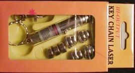
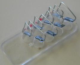
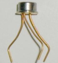
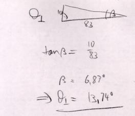
After looking for laser pointers and laser modules for some time, I found a few cheap key chain laser pointers to play around (Figure 7).
|
|
Figure 7: Cheap key chain laser pointers, sold in many retail and department stores as toys. The price was about $20 originally, but came down to about $5. |
I disassembled them by cutting off the outside aluminum tube, and extracted the laser diodes, including lens (Figure 8).
|
|
|
|
Figure 8: From these key chain laser pointers, the laser diodes are extracted.
|
|
I opened a Skyliner™ toy, and extracted the circuit board. Vadim (vadim@ml.media.mit.edu) helped me to connect the electronics of the Skyliner™ to a laser diode. First we tried to connect it directly, but the voltage was not high enough: the Skyliner™ works with 2 AA cells, so 3V. The laser pointer diodes I have need 4.5V.
Then Vadim helped me design a circuit (Figure 9, Figure 10) which uses the output of the LED wires to switch an external voltage on and off, with the help of transistors.
|
|
|
Figure 9: Circuit sketch for laser pointer diode, switched by the output of the LED via a PNP transistor |
|
|
|
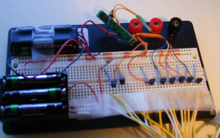
Figure 10: Breadboard with Skyliner™ electronics (green circuit board), transistors, and battery packs |
July 12, 2001
Meeting with Chris: showed him the current prototype that I made yesterday, with some laser diodes mounted on a cardboard casing. The interfacing between the Skyliner™ board and the laser pointer works properly, but the alignment of the laser beams is very bad, and the projection of the Skyliner™ is not visible.
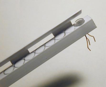
Designed two holders for the 8 laser pointers (Figure 11) on Corel 9: one with eight holes in a row, one with two rows each 4 holes. Laser cut them with 1/8-inch acrylic (100% power, 6% speed). The single row acrylic piece is going to become TinyProjector prototype 1; the two-row acrylic piece will be used later for TinyProjector prototype 2.
|
|
|
|
Figure 11: Acrylic holders for eight laser diodes; one row (left), two rows (right) |
|
With the laser diodes inserted in the holes of these acrylic pieces, the alignment of the laser beams is better, but still not good enough for a readable projection. Eric Varady (evarady@media.mit.edu, Jacky Mallet's UROP in the Garden) told me that he could help me cut threads, so that the diodes could be screwed in (the diodes come with external threads). He also told me that he could help me cut the thin mirror I have. I tried to cut one piece of the mirror myself manually, but it broke off. I made an axle for the mirror with two paper clips, and tested it quickly. It doesn't look very good: the alignment of the laser beams has to be much better.
The laser diodes from the key chain laser pointers are rather fragile: the 8th laser diode never worked, the 7th (the one we started using with Vadim) has gotten very faint.
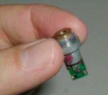
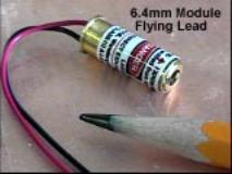
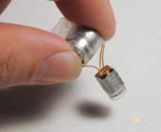
I continued the Web search for smaller laser diode modules. The smallest ones (6.4mm diameter x17.25mm long) are very expensive, though ($75), compared to the price of a cheap key chain laser pointer (between $5 and $15)
|
|
Figure 12: Small laser diode |
Laser diode modules:
- http://www.ming-micro.com/vlm_650_03.htm
- http://ioapc13.epfl.ch/Photonics/DOCS/wcd0001a/wcd01adf.htm
- http://www.lasermate.com/pl_mod.htm
- http://www.mysteries-megasite.com/main/bigsearch/laser.html
- http://www.nvginc.com/mmlaspg.htm
- http://www.misty.com/people/don/laserdon.html
July 13, 2001
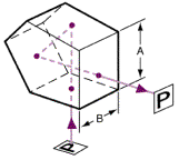
Did some Web search about prisms that could replace the little mirrors. There are penta prisms for precise 90-degree angle deviation. They would do the job, but they seem to be expensive, and probably over-sophisticated, since we don't need the non-reversing and non-inverting feature.
|
|
|
|
Figure 13: Penta prism |
|
Penta prisms:
- http://catalog.coherentinc.com/sales/Product.asp?main=3&cat=213
- http://www.oriel.com/netcat/VolumeIII/Descrippage/v3t5ptpr.htm
- http://www.casix.com/products/optics_prism_penta.htm
- http://catalog.coherentinc.com/sales/Product.asp?main=3&cat=213
However, after experimenting with flexible mirrors (foil based), it became clear that the mirrors have to be of very high quality so that they do not diffract and diffuse the laser beams too much. Therefore, it has to be either good quality mirrors, or prisms.
July 14, 2001
Tried to get another Skyliner™ at Toys'R'Us: they don't have it anymore. It seems to be available only online, e.g.:
July 16, 2001
Meeting with Chris: showed him the laser cut pieces made of acrylic that hold the 8 pointers: one where the 8 pointers are in a row, one where they are in two rows of 4.
Eric helped me looking for a tool that cuts threads into the acrylic so that the pointers are more aligned. Neither the Media Lab nor the MIT shop had metric ones with the right pitch. We decided that gluing is the only solution, but not to a single acrylic piece: I will glue each laser pointers separately to small acrylic pieces, and then screwing these pieces to a larger frame. So if one diode breaks, it can be removed from the whole and replaced with a working one.
July 18, 2001
Eric emailed his friend Josh who has more key chain laser pointers like I have. Josh said that he has only weak ones left. But that would be fine with me, just for testing.
July 20, 2001
I tried to get more laser pointers from Josh Korn (jkorn@MIT.EDU): he had 4 with him, and I told him that I would take 10.
July 21, 2001
I won an auction on eBay for more laser pointers. They were more expensive than I expected, but still dirt cheap compared to commercial 6mm diodes that cost between $70 and $140 a piece.
September 2001
September 20, 2001
Replaced three defective diodes with new ones.
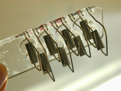
After long brainstorming with Kimiko, I decided to use a hot glue gun to attach the diodes. The advantage of hot glue over epoxy resin is that hot glue can be melted afterwards to adjust the diodes. So I glued all diodes to the acrylic holder (8 diodes in a row) (Figure 14) and calibrated them with a template on the wall, about 1.5 meters away. The calibration is not perfect, just as good as possible: it is very tricky.
|
|
Figure 14: TinyProjector prototype 1 |
Problem: Projection is not readable. Possible reasons:
(1) Getting the rotation speed of the mirror right is very tricky: if it is too slow, the human eye doesn't integrate the dots into a 2D matrix. If it is too fast, the dots become lines.
(2) Even if the right speed could be achieved, the "dead time" (inverse of duty cycle) of a full turning mirror with one or even two surface is large. E.g., if the desired projection angle is 60 degrees, then the lasers are unusable for 83% of the time! Therefore, it is not clear if a rotating mirror with one or two reflecting surfaces would work at all, without synchronizing the repetition rate with the mirror’s rotation speed.
(3) Writing is mirrored on the wall, if the Skyliner™ board is used without modification.
Possible solutions
(1) Use a dedicated PIC chip, and increase the blinking speed remarkably (reduce the time per dot). Or even better, make it adjustable: potentiometer on one A/D input of the PIC.
(2) Synchronize the rotating mirror with the character repetition rate of the lasers, possibly with a photo diode and an LED behind a hole in a wheel mounted on the mirror.
(3) Instead of one (or two) reflecting surfaces, provide three or four or even more, perhaps mounted on the outside of a tube. Like that, the dead time of the lasers would be reduced by the factor equal to the amount of surfaces per 360 degrees. Downside: the rotating element gets big.
(4) Instead of a 360-degree rotating mirror, use a mirror that does a left-right sweeping movement of, e.g., 45 degrees. Obviously, it has to be synchronized with the lasers (forward and backward writing). This is mechanically difficult, and would probably create vibration problems.
September 21, 2002 and following days
Determined the formula for calculating the projection angle given the amount of mirrors on a 360-degree tube.
Variables:
n = number of mirror surfaces per 360 degrees
p = projection angle
r = rotation speed of the mirror assembly, in Hz, for an estimated refresh rate of 4Hz
Equations:
![]()
![]()
Table 1: Number of mirrors vs. projection angles and rotation speed (Hz and rpm)
|
Mirror surfaces |
Projection angle |
Rotation Speed (Hz) |
Rotation Speed (rpm) |
|
2 |
360 |
4 Hz |
240 rpm |
|
3 |
240 |
2.7 Hz |
162 rpm |
|
4 |
180 |
2 Hz |
120 rpm |
|
5 |
144 |
1.6 Hz |
96 rpm |
|
8 |
90 |
1 Hz |
60 rpm |
|
10 |
72 |
0.8 Hz |
48 rpm |
|
12 |
60 |
0.4 Hz |
24 rpm |
|
|
|
|
|
|
|
|
|
Figure 15: Four mirror surfaces per 360 degrees (left), five mirrors (middle), eight mirrors (right) |
||
However, several issues have to be mentioned:
Issue 1:
Given an estimated optimal refresh rate of 4 Hz (four sweeps per second) of the original Skyliner™ toy, the rotation speed of a cylinder will be low, which would require a high-reduction gearbox for the motor. Of course a higher refresh/sweep rate would be better, but then the laser pulse time per dot has to be reduced remarkably. The question is how short the laser pulses can be, given the PIC and the transistors.
Issue 2:
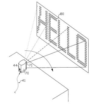
If the beams point to the center of the rotating mirrors (more precisely: to the axis of the tube inside the mirrors), the laser diodes themselves will obstruct part of the projection. Therefore, the projection axis of the laser beams has to be displaced by a few millimeters to one side, away from the center of the rotating mirrors, so that the mirrors deflect the beams to the side, e.g., for about 90 degrees (see Figure 16).
Issue 3:
The biggest disadvantage of having eight or more reflecting surfaces is that the rotating mirror assembly gets bulky. (This issue will turn out to be the main reason to abandon the multiple surfaces mirror design.)
|
|
|
|
Figure 16: Eight-faced mirror with a linear laser array of 8 lasers, slightly displaced |
|
October 2001, 1st – 7th
October 2, 2001
In order to test the design hypotheses, I am making two 8-sided mirrors, with stainless steel strips (1/2 inch wide), and a Styrofoam core (see Figure 17).
October 3, 2001
I tested many glue types (rubber cement, white glue, plastic two component, epoxy two component) to see how to glue the mirrors to the Styrofoam: epoxy resin works best.
I completed the 8-faced rotating mirror pillar, and added a motor (with 9V battery and on/off switch) by Lego. Works much better than by hand, but the projection is still not readable.
Possible reasons for the bad projection:
- The alignment of the laser beams is rather bad. Since the eight laser beams to not form a straight row of dots, a readable projection is impossible.
- The speed of the rotating mirror is too fast: the dots become lines. Reducing the pulse time of the lasers can solve this problem.
- The refresh rate is still too low. Basically, the brightness of the laser diodes is too low for a projection angle of 90 degrees (which is invariably coupled to the 8-faced mirror).
|
|
|
Figure 17: First prototype with 8-faced mirror with Lego motor. |
The above limitations are severe. After having seen the prototype in action, I decide to change the design completely.
The next prototype I will design with a mirror that moves from left to right and back, driven by a servo. The advantage is having a smaller mirror, while still having a full 100% duty cycle of the laser beams.
|
|
|
|
Figure 18: Linear array of 8 laser diodes, with single surface mirror mounted on a central axle |
|
However, such a construction has the following issues:
- Vibration will occur, since the rotation (angular movement) is not continuous, but changing back and forth.
- Closed loop necessary: The lasers beams have to be synced with the position of the mirror since they have to know when to start projecting.
- More complex computation: In order to obtain 100% duty cycle, the lasers have to be able to write from left to right, as well as from right to left.
- Sinusoid movement of
mirror is bad: It would
be easy to have a sinusoid movement of such an assembly, for example with
a crank on a small motor. But a non-constant speed of the laser sweeps
will be difficult to compensate with the pulse lengths. Therefore, in
order to have constant speed of the sweeps, the mirror has to be driven
with a square wave movement. (Basically, the speed of the mirror has to be
constant over the whole projection range, and can’t slow down at the
turning points. But that’s exactly what would happen with a simple crank
on a motor as the actuator.)
A simple implementation of such a back-and-forth movement could use a micro servo, like the WES2.4 or the Hitec HS-50 (Figure 19). The servo could be controlled directly by a PWM generated by the PIC chip (which is relatively trivial). The advantage would be that the positioning of the mirror could be controlled very accurately, and as a consequence also the rotation speed.
|
|
|
|
Figure 19: WES-2.4 servo (left), Hitec HS-50 (right) |
|
Furthermore, synchronizing the mirror with the laser pulses is doable, because the PIC chip that generates the pulses also defines the position of the mirror.
The downside of using a servo is that it is relatively noisy and power hungry (100mA). In addition, the maximum sweep time (left to right, 60 degrees) of these servos is 0.2 sec (WES) and 0.09 sec (Hitec). The sweep time of the mirror however could be increased easily by gearing up the connection between the servo and the mirror, e.g., by using only 30 degrees (or less) of the servo deflection to rotate the mirror 90 degrees. This will work if the forces involved in turning the mirror are very small, which requires a very light going hinge of some kind.
In addition to having a left-right sweeping mirror, the next prototype will have another improvement: it will be much smaller. In the current prototype, the overall length of the assembly is given by the linear array of 8 lasers, which in turn is given by the diameter of the laser diodes.
Since I do not have access to a miniature commercial laser array (e.g., Honeywell), the outer diameter of my laser diodes dictates the minimum length of the array. With a casing that has a diameter of 11 mm, the minimum length will be 88mm. However, the laser beams could have been closer to each other, since the diameter of the beams is only about 3mm.
Therefore, in order to reduce the overall width, I intend to build a holder for two rows of four lasers, where the two rows are slightly offset. To align them, small secondary mirrors are necessary. Like that, the two rows of laser beams get directed to the main mirror (left-right sweeping) as a single row (Figure 20, Figure 21).
|
|
|
Figure 20: Design with two rows of 4 laser diodes |
|
|
|
Figure 21: The two rows are set off by about 6mm, and therefore need a set of secondary mirrors (on the left side) to align the laser beams to a single row, which will then hit the main mirror (right side). |
I need the small secondary mirrors to align the planes of the two rows of lasers. Therefore, I bought many different kinds of tiny mirrors, beads and stainless steel strips, at the Pearl Arts and Crafts store in Cambridge.
I conducted several tests of how to assemble small mirrors, made of stainless steel strips and paperclip wire, for the 90-degree deflection of the two-row laser pointer assembly.
October 4, 2001
I worked on the TinyProjector prototype 2: I cut some Acrylic parts on the lasercutter (lower part, containing servo), manufactured eight miniature mirrors, made of stainless steel and paper clips, and glued everything together with epoxy resin (Figure 22).
|
|
|
|
|
|
Figure 22: Assembly with two rows of 4 mirrors
|
|
October 5, 2001
I borrowed a PIC programmer (Figure 23) from Bakhtiar Mikhak (mikhak@media.mit.edu), and a serial cable that works with it from the Borglab.
|
|
Figure 23: PIC programmer
|
I have programmed PICs many times before already: for my Free Flying Micro Platform project, I used several PICs, some for creating the PWM signal to the RC handset, some for reading the two analog signals of the micro compass and creating a heading angle, and then transmitting this angle over the serial wired port, both wired and with a transceiver. But that is already some years ago, so I had to refresh my memory.
PIC programming tutorials:
- http://www.rentron.com/Myke3.htm
- http://www.phanderson.com/PIC/PICC/
- http://www.gvu.gatech.edu/ccg/resources/pic/
In order to control a servo, I need to create the right pulse width modulation (PWM) with the PIC.
· http://www.inchlab.com/2servo_interface.htm
First try for pseudo code for the PIC controller (no serial input):
Message = (T, H, I, S, _, I, S, _, A, _, T, E, S, T)
For all characters of message:
set servo PWM to minimum (servo goes to full left position)
look up character pattern, blink lasers for 5 time slots each
For all characters of message:
set servo PWM to max (servo goes to full right position)
look up character pattern, blink lasers in reverse for 5 time slots
Code for PIC: with serial input
- Read char
if char is sync char (0xFF)
for 30 characters:
read char
October 6, 2001
More useful information about writing PIC code:
· http://www.ccsinfo.com/v3.txt
· http://www.ccsinfo.com/overview.html
Then I soldered the diodes to the multi-line cord (Figure 24), calibrated the mirrors, and set up the second breadboard.
|
|
|
|
Figure 24: TinyProjector prototype 2: Lower part of laser diode holder. The diodes had to be inserted before soldering them to the multi-line cord. Visible is also the gray foam layer for reducing vibration sensitivity, as well as white tape to isolate the casings of the diodes from each other (see isolation problem, October 7, 2001). |
|
October 7, 2001
I solved code bugs: calibration, length of signals (pulse, spaces between pulses, space between characters, number of characters, servo elevation)
Hardware problem: The servo PWM getting jammed if PIC turns on more than 4 laser pointers. Solution: it needs 1K resistors between the B pins and the transistors. (Many thanks to Matt Reynolds, matt@media.mit.edu!)
Isolation problem: Laser 5 and 7 always were lighting up simultaneously—they couldn’t be controlled independently. After a long time, I found out that this is because the metal shells are connected to the positive tab of the diode, and the two diodes were touching each other. So current to one laser turned on the other, too. I took the whole assembly apart and isolated the shells of the diodes. (Again, many thanks to Matt Reynolds who mentioned this fact to me actually much earlier—I just forgot about it.)
|
|
|
Figure 25: Final circuit design of TinyProjector prototype 2, with additional 1KOhm resistor between the transistors and the PIC |
Character set
To create the character fonts, I first thought I would be able to find them on the Web. Here are some related sites about character set fonts (5x8, 5x7):
- http://www.myfonts.com/CharacterMap34282.html
- http://www.rabbitsemiconductor.com/documentation/docs/refs/TN211/TN211.htm
Eventually, however, I ended up designing my own fonts. I was using a grid printed on a paper, then drew a big character on top of that, and then extracted the dots that are necessary to display the character (Figure 26).
|
|
Figure 26: Font template for a 10x8 (high resolution) character "N". For the actual projection, see Figure 28) |
[Note: I didn't sleep that night, went home Monday morning at 9:30am and slept Monday 10am - 2pm.]
October 2001, 8th – 16th
October 8, 2001
I tried to set up a serial connection to the Palm Pilot. It didn't work, even after inserting resistors into RS232 pins on PIC.
- http://vbmhome.cjb.net/
- http://academic1.bellevue.edu/robots/16f84lcd.html
- http://www.odsa.com/tools/ascii.shtm
- http://hamjudo.com/sonar/
C code for TinyProjector prototype2
Since the serial connection did not work at this time, I made the projector go through a sequence of a few different projections (Figure 27).
|
#include <16F84.h> #fuses HS,NOWDT,NOPROTECT,PUT #use Delay(Clock=10000000) #use fast_io(A) #use fast_io(B) #use RS232(Baud=38400,Xmit=PIN_A1,Rcv=PIN_A0,parity=n,bits=8) #byte PORTA = 5 #byte PORTB = 6 #define SERVO PIN_A2
int v; char char1 = 's';
void delay_10us(int i) { do {delay_us(10); } while(--i); }
// character projection routines void project_A(int forward) { for (v=0; v<5; v++) { if ((v==0)||(v==4)) { PORTB = 0b00000001; } if ((v==1)||(v==2)||(v==3)) { PORTB = 0b11101110; } delay_us(1100); PORTB = 0xFF; delay_us(1000); } }
void project_C(int forward) { if (forward==1) { for (v=0; v<5; v++) { if (v==0) { PORTB = 0b10000001; } if ((v==1)||(v==2)||(v==3)) { PORTB = 0b01111110; } if (v==4) { PORTB = 0b10111101; } delay_us(1300); PORTB = 0xFF; delay_us(1000); } }else{ for (v=0; v<5; v++) { if (v==0) { PORTB = 0b10111101; } if ((v==1)||(v==2)||(v==3)) { PORTB = 0b01111110; } if (v==4) { PORTB = 0b10000001; } delay_us(1300); PORTB = 0xFF; delay_us(1000); } } }
void project_O(int forward) { for (v=0; v<5; v++) { if ((v==0)||(v==4)) { PORTB = 0b10000001; } if ((v==1)||(v==2)||(v==3)) { PORTB = 0b01111110; } delay_us(1100); PORTB = 0xFF; delay_us(1000); } }
void project_L(int forward) { if (forward==1) { for (v=0; v<5; v++) { if (v==0) { PORTB = 0b00000000; } if ((v==1)||(v==2)||(v==3)||(v==4)) { PORTB = 0b01111111; } delay_us(1300); PORTB = 0xFF; delay_us(1000); } }else{ for (v=0; v<5; v++) { if ((v==0)||(v==1)||(v==2)||(v==3)) { PORTB = 0b01111111; } if (v==4) { PORTB = 0b00000000; } delay_us(1300); PORTB = 0xFF; delay_us(1000); } } }
void project_N_hires(int forward) { if (forward==1) { for (v=0; v<10; v++) { if ((v==0)||(v==1)) { PORTB = 0b01111110; } if ((v==2)||(v==8)) { PORTB = 0b00000000; } if (v==3) { PORTB = 0b01111001; } if (v==4) { PORTB = 0b01110011; } if (v==5) { PORTB = 0b11100111; } if (v==6) { PORTB = 0b11001110; } if (v==7) { PORTB = 0b10011110; } if (v==9) { PORTB = 0b11111110; } delay_us(700); PORTB = 0xFF; delay_us(1000); } }else{ for (v=0; v<10; v++) { if ((v==9)||(v==8)) { PORTB = 0b01111110; } if ((v==7)||(v==1)) { PORTB = 0b00000000; } if (v==6) { PORTB = 0b01111001; } if (v==5) { PORTB = 0b01110011; } if (v==4) { PORTB = 0b11100111; } if (v==3) { PORTB = 0b11001110; } if (v==2) { PORTB = 0b10011110; } if (v==0) { PORTB = 0b11111110; } delay_us(700); PORTB = 0xFF; delay_us(1000); } } }
void project_EXCLAMATION(int forward) { for (v=0; v<5; v++) { if ((v==0)||(v==1)||(v==3)||(v==4)) { PORTB = 0b11111111; } if (v==2) { PORTB = 0b01100000; } delay_us(1100); PORTB = 0xFF; delay_us(1000); } }
void project_SPACE(int forward) { for (v=0; v<5; v++) { PORTB = 0b11111111; delay_us(1100); PORTB = 0xFF; delay_us(1000); } }
main() { int k, m, u, s; set_tris_a(0b00000001); set_tris_b(0b00000000);
while(1) { for (u=0; u<10; u++) { // write "cool" six times for (k=0; k<15; k++) { OUTPUT_HIGH(SERVO); delay_us(1900); OUTPUT_LOW(SERVO); delay_ms(3); if (k==0) { project_C(1); } if (k==1) { project_O(1); } if (k==2) { project_O(1); } if (k==3) { project_L(1); } if (k==4) { project_EXCLAMATION(1); } if (k==5) { project_SPACE(1); } if (k==6) { project_C(1); } if (k==7) { project_O(1); } if (k==8) { project_O(1); } if (k==9) { project_L(1); } if (k==10) { project_EXCLAMATION(1); } if (k==11) { project_SPACE(1); } if (k==12) { project_C(1); } if (k==13) { project_O(1); } if (k==14) { project_O(1); }
delay_us(1300); }
for (m=0; m<15; m++) { OUTPUT_HIGH(SERVO); delay_us(1000); OUTPUT_LOW(SERVO); delay_ms(2); if (m==0) { project_O(0); } if (m==1) { project_O(0); } if (m==2) { project_C(0); } if (m==3) { project_SPACE(0); } if (m==4) { project_EXCLAMATION(0); } if (m==5) { project_L(0); } if (m==6) { project_O(0); } if (m==7) { project_O(0); } if (m==8) { project_C(0); } if (m==9) { project_SPACE(0); } if (m==10) { project_EXCLAMATION(0); } if (m==11) { project_L(0); } if (m==12) { project_O(0); } if (m==13) { project_O(0); } if (m==14) { project_C(0); }
delay_us(1300); } } // end of cool
delay_ms(500); for (u=0; u<10; u++) { // write "A" six times
for (k=0; k<15; k++) { OUTPUT_HIGH(SERVO); delay_us(1900); OUTPUT_LOW(SERVO); delay_ms(3); project_A(1); delay_us(1300); }
for (m=0; m<15; m++) { OUTPUT_HIGH(SERVO); delay_us(1000); OUTPUT_LOW(SERVO); delay_ms(2); project_A(0); delay_us(1300); }
} // end of AAA
delay_ms(1000); for (u=0; u<10; u++) { // write "N" hires for (k=0; k<15; k++) { OUTPUT_HIGH(SERVO); delay_us(1900); OUTPUT_LOW(SERVO); delay_ms(3); project_N_hires(1); delay_us(1300); }
for (m=0; m<15; m++) { OUTPUT_HIGH(SERVO); delay_us(1000); OUTPUT_LOW(SERVO); delay_ms(2); project_N_hires(0); delay_us(1300); }
} // end of NNN hires delay_ms(1000);
} // end of main while loop } // end of main |
|
Figure 27: C code for TinyProjector prototype 2 |
After a lot of tweaking, the projection of the second prototype seems acceptable to me. The refresh rate is about 3Hz, which means it relies on Persistence of Vision principles. [This will not be the case anymore in the next prototype.]
|
|
|
|
Figure 28: Two projections: a row of "A" characters (left), and a row of high resolution "N" (right) |
|
After the demo started to work properly, I still had to design a poster (which first required installing software on a laptop, like Thumbs and Photoshop).
First I made some hand drawings (Figure 29), and digitized them.
|
|
|
|
|
Figure 29: Drawings for poster
|

Then I took tons of pictures of the prototype (Figure 30).
|
|
|
|
|
|
||
|
|
|
|
|
Figure 30: Working TinyProjector prototype 2 |
||
After designing the poster (Figure 31), I had to fix the plotters (I actually did both Hammersmith and Lenz), printed it out, cut it manually, and spray-glued it onto cardboard.
|
|
|
Figure 31: Final poster for Fall 2001 sponsor meeting |
[Note: I did not sleep this night either, only October 9 afternoon from 2pm till 7pm.]
|
|
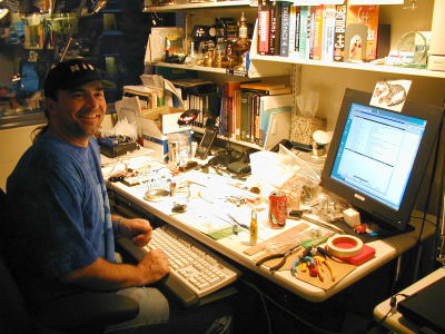
Figure 32: Me in my office, one of my work areas |
October 9, 2001
Demoed TinyProjector prototype 2 9:30 – 12:30 during I/O Open House at the MIT Media Lab.
|
|
Figure 33: Me demoing during the I:O sponsor open house |
October 11, 2001
I demoed TinyProjector prototype 2 from 15:00 – 18:00, during Digital Life open house.
I replaced 7 laser diodes after I accidentally connected 4.8V (power supply!) instead of 4.5V: four of them were down to 20% brightness; three more broke later. (The original idea I had was to start the laser projector demo with a Clapper! But in order to use the Clapper, I had to use a power supply instead of the 3 alkaline cells. Unfortunately, the power supply had 4.8V instead of 4.5V…)
During these extensive repairs, I had an idea: In order to speed up the repair time, why don’t I just screw the laser diodes into the acrylic? And don't solder the contacts, but just clip the cables on. (I never implemented this idea.)
Credits: These people helped me with the second prototype of TinyProjector:
o Deva Seetharam (deva@media.mit.edu): for the idea that we had during the Tangible interfaces class in October 2000
o Natalia Marmasse (nmarmas@media.mit.edu): C problems, circuit problems
o Vadim Gerasimov (vadim@media.mit.edu): original circuit design
o Rob Poor (r@media.mit.edu), Matt Reynolds (matt@media.mit.edu), and hackers on hackers mailing list: electronics details
o Bakthiar Mikhak (mikhak@media.mit.edu): PIC programmer
o Borglab: cables
o Hannes Vilhjalmsson (hannes@media.mit.edu) and GNL (wires, foam)
Feedback from interactions during open house:
- The Private Eye (like
Bradley Rhodes has been wearing) is based on the same principle: a row of
red LEDs and a vibrating mirror:
http://www.ndirect.co.uk/~vr-systems/priveye1.htm
- Matt Reynolds (matt@media.mit.edu) suggests using smaller mirrors that are balanced, and probably require a far smaller servo. [I will follow this suggestion during design of the next prototype.]
October 16, 2001
I met with Sloan Kulper (sloan@media.mit.edu) from John Maeda's group. I showed him my demo, and he told me what he is working on, which is very related (http://acg.media.mit.edu/people/sloan/June.html/index.html).
We were talking about the novelty of our work, and started to look into the US Patents database. Indeed, we found a long list of very related work:
Most of these patents are based on persistence of vision projection with LEDs, (like for the Skyliner™ and the Private Eye. For example, patent number 4470044 (Figure 34):
“Momentary visual image apparatus
A modulated array of lights for the creation of momentarily perceptible visual images when scanned asynchronously by the human eye during characteristic saccadic eye movements between points of eye fixation is described in the disclosure. The array and modulation style are chosen to provide an image that matches the span of the human eye/brain combination for recognition of tachistroscopically presented lines of text, other symbols, and pictorial images, and to achieve an illusory effect wherein the momentary image appears dissociated from the array of lights and appears superimposed on the scene of eye fixation just prior to initiating the saccadic movement. A preferred embodiment using light emitting diodes and large-scale integrated logic circuitry is described for generation of words, phrases up to 32 characters long, and simple pictures.”
(Patent filed May 15, 1981, awarded September 4, 1984.)
|
|
|
|
|
|
|
Figure 34: Patent 4470044 |
|
The illustrations speak for themselves. Most of the other patents are very similar.
However, the patent number 6222459 is different because is explicitly mentions laser diodes, and is therefore very close to my work (Figure 35):
“Method of word screen formation by laser light projection and the structure for the same
The present invention relates to a method of word screen formation by laser light projection and the structure of word formation by laser light projection, and in particular, relates to a plurality of laser production devices arranged in a single column and by rapid reciprocating action of the devices to project multiple columns of light track and form word arrays.”
(Patent filed July 22, 1999, awarded April 24, 2001)
|
|
|
|
|
|
|
Figure 35: Patent 6222459 |
|
Up to that point, there is still the rotating mirror concept missing, but the very last illustration/claim describes exactly this variation of the above projector (Figure 36):
|
|
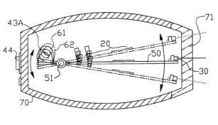
Figure 36: Patent 6222459, third last paragraph: “In another preferred embodiment of the present invention (…) the lateral edge of the board body 50 and the inner wall of the two lateral edges of the housing 72 are in engagement with each other, and adjacent to the board body 50, is a plurality of laser production devices 30, 31, 32 are mounted. At the laser port, the reciprocating mechanism 60 driven by the power source 40 is provided. The power source 40 is an electrical source 41 connected in series to a switch 44, and the reciprocating mechanism 60 is a reciprocating swinging type electric motor 63 connected to a speed-adjusting element 43. The center of the output shaft of the speed-adjusting element 43 is provided in vertical with a reflection mirror 64. The electric motor 63 is electrically connected to the power source 40 and the reflection surface of the reflection mirror 64 faces the laser port of the laser production devices 30, 31, 32, such that the laser light emitted from the laser port is directed to the reflective mirror 64 while the mirror 64 is swinging, and the light is reflected through the housing window 71 to the column position, where the projection face corresponding to the lighted word screen, and forms lighted word tracks.” |
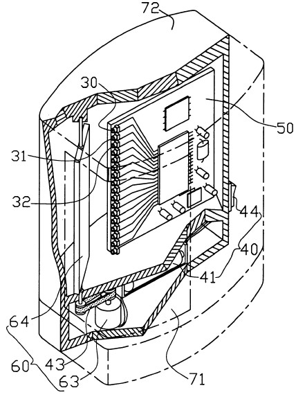
Claim 5 pretty much describes the full rotational two-faced mirror version of my idea.
However, as I will describe later in this lab notebook, a system with such a mirror design is very inefficient and can work only with very high power laser diodes since with such a mirror configuration, the duty cycle of the lasers is far from optimal.
I wonder if the inventor of this patent, Mr. Chih-Yu Ting from the Taiwanese company OPCOM Inc. (http://www.opcomgroup.com/main.htm), a laser and CCD products producer, has actually built the projector described in claim 5. I doubt it very much.
Note that this patent was awarded after I started working on this project.
March 2002, 1st – 21st
March 7, 2002
After a six-month break during which I had to attend other business (my qualifying exam, basically), we decided to continue the work on the TinyProjector.
I had a 3-hour brainstorming with Wilfrido Sierra (wsierra@media.mit.edu) and Jonathan Brill (jonathanbrill@hotmail.com) about the design of a new projector.
Will showed me his laser diodes (6$, from Honeywell; not (yet) publicly available, he got them via Mike Bove, http://content.honeywell.com/vcsel/pdf/sv3644-001.pdf, see Figure 37), and his laser array (with the custom-molded lens array).
|
|
Figure 37: Red VCSEL component (preliminary) |
He was interested in the lenses I have, scavenged from the cheap key chain laser pointer diodes, so I gave him three of mine. My diodes (without casing and lenses) break very fast and seem very sensitive to vibration; his seem to be more rugged.
I also made a distance holder from a square aluminum tube for a single Honeywell VCSEL diode and an old lens (about 8mm distance). The lens is not symmetric, though; the round part has to look away from the diode. The voltage is 2.3 -2.7V, and it seems to be resistant to under and over voltage (it just doesn't work if not the right voltage). Used two old LR44 button batteries (total about 2.7V) to power it. Brightness is much less than old laser diode, but in a much smaller package (Figure 38).
|
|
|
|
Figure 38: Honeywell laser diode with aluminum tube holder and two lithium button cells
|
|
I also made a mockup of a plastic square tube (diameter has almost the right distance to hold the lens in right distance from the diode) that could hold all 8 diodes/lenses (replacing the single aluminum square tube) (Figure 39).
|
|
Figure 39: Mock-up with ABS square tube: front side (top), and back side (bottom)
|
|
|
I also did a Web search for PIC controllers that have bigger memory than the 16F84: looks like the 16F87 and 16F88 have four times the memory, and seems to be pin compatible with the 16F8's. However, unfortunately, they have status "future product"…
http://www.microchip.com/download/lit/pline/picmicro/families/16f8x/39568b.pdf
I found some example code for the 16F87X, which uses the CCS and has arrays in it: http://www.phanderson.com/icd/PIC16F87X_tutorial_sample.pdf
Then I wrote some PIC code that is more systematic than the old one, trying to optimize the algorithm of creating the patterns (Figure 40):
|
#include <16F84.h> #fuses HS,NOWDT,NOPROTECT,PUT #use Delay(Clock=10000000)
#use fast_io(A) #use fast_io(B)
#use RS232(Baud=38400,Xmit=PIN_A1,Rcv=PIN_A0,parity=n,bits=8,INVERT)
#byte PORTA = 5 #byte PORTB = 6
#define SERVO PIN_A2
char message[12] = {"H","E","L","L","O"," ","W","O","R","L","D","!"};
byte _A[5] = { 0b00000001, 0b11101110, 0b11101110, 0b11101110, 0b00000001 };
byte _B[5] = { 0b00000000, 0b01110110, 0b01110110, 0b01110110, 0b10001001 };
byte _C[5] = { 0b10000001, 0b01111110, 0b01111110, 0b01111110, 0b10111101 };
byte _D[5] = { 0b00000000, 0b01111110, 0b01111110, 0b01111110, 0b10000001 };
byte _E[5] = { 0b00000000, 0b01110110, 0b01110110, 0b01110110, 0b01111110 };
byte _F[5] = { 0b00000000, 0b11110110, 0b11110110, 0b11110110, 0b11111110 };
byte _L[5] = { 0b00000000, 0b01111111, 0b01111111, 0b01111111, 0b01111111 };
byte _O[5] = { 0b10000001, 0b01111110, 0b01111110, 0b01111110, 0b10000001};
byte _EXCL[5] = { 0b11111111, 0b11111111, 0b01100000, 0b11111111, 0b11111111 };
byte _SPACE[5] = { 0b11111111, 0b11111111, 0b11111111, 0b11111111, 0b11111111 };
void project3(byte the_character[], int the_line) {
PORTB = the_character[the_line]; delay_us(1300); PORTB = 0xFF; delay_us(1000); }
void project2(char c, int line_number) { if (c == 'A') {project3(_A,line_number); } if (c == 'B') {project3(_B,line_number); } if (c == 'C') {project3(_C,line_number); } if (c == 'D') {project3(_D,line_number); } if (c == 'E') {project3(_E,line_number); } if (c == 'F') {project3(_F,line_number); }
if (c == 'L') {project3(_L,line_number); } if (c == 'O') {project3(_O,line_number); } if (c == '!') {project3(_EXCL,line_number); } if (c == ' ') {project3(_SPACE,line_number); }
}
void project1(char the_char, int forward) { int v;
if (forward==1) { for (v=0; v<5; v++) { project2(the_char, v); } }else{ for (v=5; v>0; v--) { project2(the_char, v); } } }
main() { set_tris_a(0b00000001); set_tris_b(0b00000000); int i; int forw;
for (forw=1; forw>=0; forw--) { for (i=0; i<12; i++) {
OUTPUT_HIGH(SERVO); if (forw==1){ delay_us(1900); } else { delay_us(1000); }
OUTPUT_LOW(SERVO);
if (forw==1) { delay_ms(3); } else { delay_ms(2); }
project1(message[i],forw);
delay_us(1300); } } |
|
Figure 40: New C code for second prototype, with simpler and clearer algorithm (new.c) |
March 11, 2002
I had a meeting with Chris about the TinyProjector.
I updated him on new diodes from Mike: could make a simpler, more robust, and smaller prototype.
We should focus on interaction modes: RSVP, scrolling, etc. Find good applications (or scenarios).
It will be a closed project, done after I have made it work.
He asks: Will it be loud? Probably.
In order to make it quieter, I was thinking about using a magnetic actuator to move the mirror, like a BIRD, CETO, or a MiniMag actuator:
- http://www.rcmicroflight.com/may00/cloud9_03.asp
- http://www.hobbyclub.com/rcCetosyst.htm ($35)
- http://www.ruijsink.nl/mm-hoofd.htm
- http://www.ruijsink.nl/images/mm/gr/Dl4.jpg (36 Euro)
I asked Mike Bove (vmb@media.mit.edu) about more diodes at: http://content.honeywell.com/vcsel/pdf/sv3644-001.pdf
He says, Honeywell does not have a lot of them, but if he gets more, and Will doesn't need them, I can have them.
I should ask Will what he plans to show for the Spring open houses, so that I don’t do something that he shows also.
March 14, 2002
I simplified the servo idea drastically: instead of a normal servo, why not using a 2V Ballooncraft motor that is limited left and right after 90 degrees, and drives the mirror directly? A PIC output pin high means turn left, pin low means turn off (and rubber band takes the mirror back) or turn right (but how to turn the motor off completely? Using two pins?)
I thought a lot about simplifying even more:
- Have the motor turn 360 degrees and move the mirror back and forth, like a steam machine. Disadvantage: sinusoid movement; PIC needs to know where the mirror is.
- Have the motor turn the mirror directly 360 degrees. Disadvantage: Direct drive perhaps too fast: does it need gears, or just very low voltage? PIC needs to know where the mirror is. Perhaps via magnetic sensor, or via light sensor and LED?
Questions for Vadim:
- Serial connection problem (not solved until now): would INVERT help the serial I/O? Or do I need more, like a resistor?
- If a pin is set high, will it stay high until it is set otherwise?
March 15, 2002
I made rotating mirror prototype with a small pager motor (Mabuchi J20WA, by Ballooncraft, http://www.toytx.com/6mm13vpagmot.html) (Figure 41).
|
|
Figure 41: Pager motor Mabuchi J20WA (6mm diameter) |
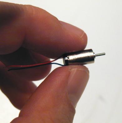
The sides and the mirror holders are made of balsa wood. The base is made of ABS. The performance is surprising: the motor, driven with 1.5V, spins the mirror, a 1/2 inch x 55mm stainless steel strip, nicely, if the sidewalls are aligned perfectly. And it is amazingly quiet! (Figure 42)
|
|
|
Figure 42: full rotation two-faced mirror balsa test assembly |
Main problem with this design: the mirror might not be torque resistant enough. [My solution later will be: use two mirrors, and a steel rod in the middle.]
Next I opened four very old computer mice in order to examine their opto-mechanical shaft encoders (Figure 43).
|
|
Figure 43: Inside the MS Trekker mouse, there is a set of photodiode/IR LED that I unsoldered (the photodiode is already removed on this picture). Below the IR LED. |
|
|
Then I had a meeting with Vadim:
To control a motor backwards/forwards, use a specific chip, e.g., L293D. Two pins of the PIC would control it: the first makes it move in one direction, the second in the other. Do I have two free pins?
http://www.alltronics.com/download/1330.pdf
Connect one pin to ENABLE1 and the other to ENABLE2, and then take the voltage from OUTPUT (where exactly?)
PIC with more memory: 16F877 (there are more models coming, but not available yet). Very big, but has more memory, and there is a surface mount version.
For rotating mirrors: I need a shaft encoder plus IR LED, perhaps take it from a mouse. These components are probably already digital, so they can be fed into PIC.
http://www.didel.com/microkit/Prix.html
http://www.didel.com/microkit/Encoder.html
Optical encoders by HP:
http://www.micromo.com/images/HEDL_5500_3.PDF
Optical encoder by Honeywell:
http://content.honeywell.com/sensing/prodinfo/infrared/application/ap_00031.pdf
http://content.honeywell.com/sensing/prodinfo/infrared/application/In8eng.pdf
Optical encoder by Omron:
http://oeiweb.omron.com/oei/PDF/D21SX198199199.pdf
Other:
http://www.robologic.co.uk/tutadvshaft.htm
Small Bluetooth chip:
http://www.alps.co.jp/press/new2002/0228-e.htm
Recycled angle-sensor:
http://www.convict.lu/Jeunes/Recycled.htm
Rotary Encoders tutorial:
http://www.ubasics.com/adam/electronics/doc/rotryenc.shtml
March 18, 2002
Meeting with Vadim: We tried to figure out how the IR LED and the photoreceptor of the Microsoft Trekker mouse are used.
The IR pulses, and the two receptors (probably vertically) pick it up. I don't need the pulsing (which was used for lower power consumption), and just one receptor.
The middle pin of the receptor has +5V, either of the outer pins can be used to connect to the PIC. A 20K resistor has to be connected between the pin/PIC connection and ground.
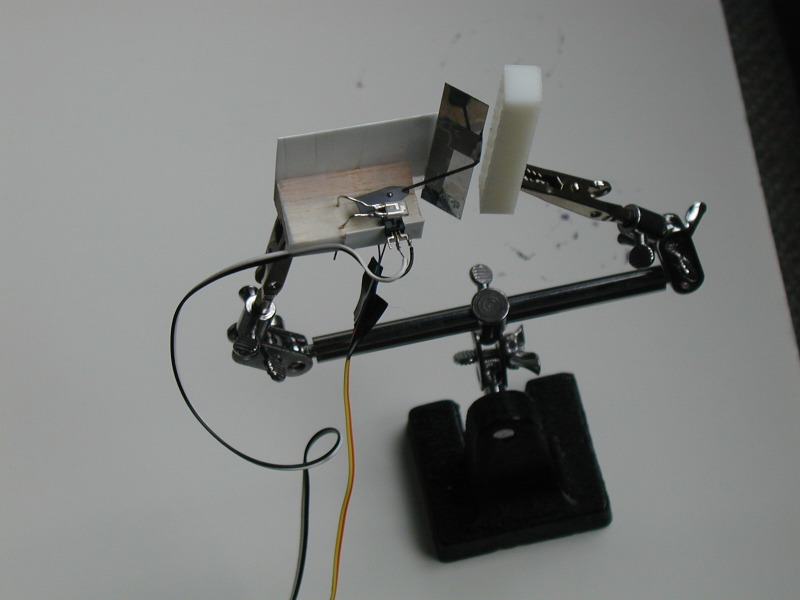
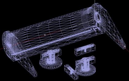
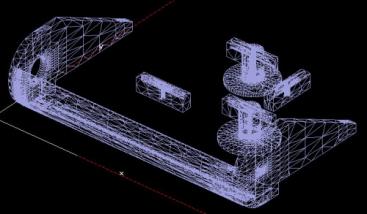
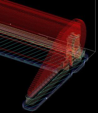
Then I built 3D models of TinyProjector prototype 3 (Figure 44): a rotating two-faced mirror add-on for the second prototype. It uses the before mentioned stainless steel strip (1/4th inch x 55mm).
I also modeled the laser diodes and lenses, all to scale.
|
|
|
|
|
|
|
|
|
|
|
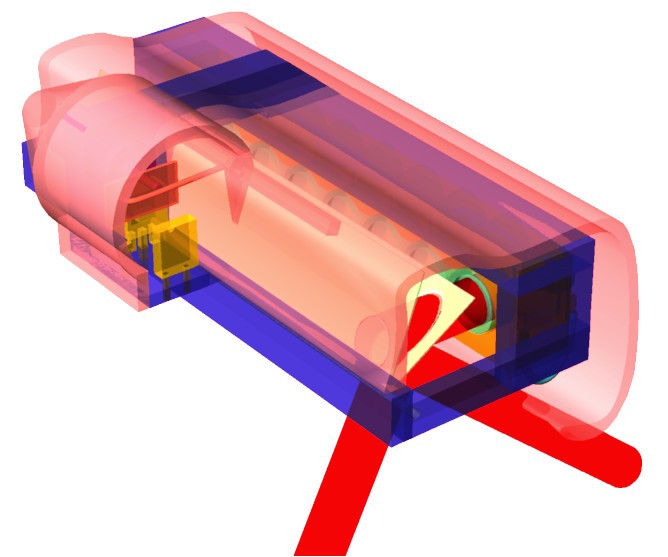
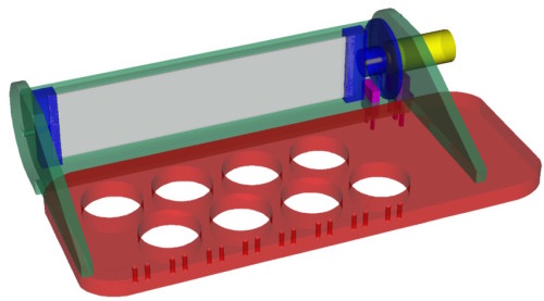
Figure 44: 3D model of full rotating mirror assembly as add-on to prototype 2; the existing acrylic plate for holding the laser diodes is red; IR LED and the photoreceptor are purple; the pager motor is yellow; mirror holder elements are blue; rest of housing is green; mirror made of stainless steel stripe is gray. |
March 21, 2002
I installed Rhino2 (which can write STL files), and Quickslice (at home and at the lab, requires higher display resolution than laptop can go). Played around with 3D model of TinyProjector prototype 3 (base, slicing, etc).
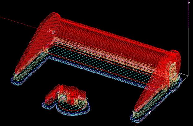
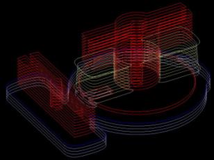
The following screenshots (Figure 45, Figure 46, Figure 47) are from Quickslice, the program that takes the 3D model (e.g., from Rhino, see above), and generates the slices and paths for the 3D printer.
|
|
|
|
|
|
|
|
|
Figure 45: Solid renderings by Quickslice |
||
|
|
|
|
|
|
|
Figure 46: Wire frame models used by Quickslice |
|
|
|
|
|
|
Figure 47: The slices and paths generated by Quickslice. The actual plastic element is red (ABS), supporting material is green, and the base is blue |
March 2002, 22nd – 31st
March 22, 2002
3D printed TinyProjector prototype 3 on our Stratasys FDM 2000 with the following settings:
Material: ABS P400
Alternate Material: P400-SR Soluble
Heads: both T16
Slice size: 0.014
March 25, 2002
I cleaned the 3D printed parts in ultrasonic bath.
Then I drilled holes in the turning parts: although they were part of the 3D printed model, the holes did not come out properly and had to be re-drilled.
|
|
|
|
Figure 48: 3D printed model |
|
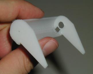
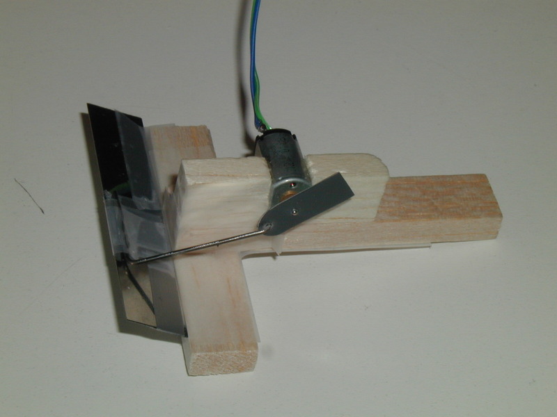
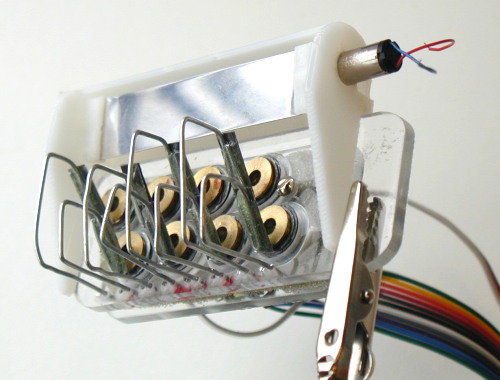
The following pictures (Figure 49) show the 3D printed parts, fully assembled with the pager motor (Mabuchi J20WA), and the stainless steel mirror. The axle on the opposite side of the motor is a simple steel rod. For size comparison: overall size of the assembly is 68mm, and the motor has a diameter of 6mm.
|
|
|
|
|
|
|
Figure 49: Fully assembled add-on to prototype two |
|
|
|
Figure 50: Mirror holder, mirror, and motor |
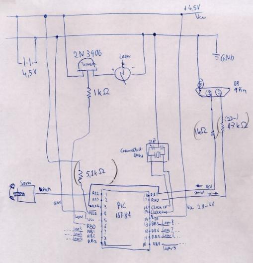
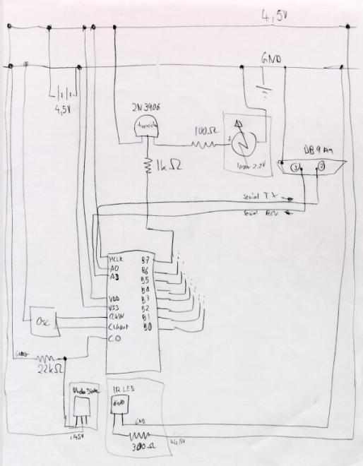
Later I sketched out the schematics for the current projector, determining which pins are for serial, what are the values of the resistors, which pins on the PIC are free, etc (Figure 51).
|
|
|
Figure 51: Schematic of prototype 3 |
March 26, 2002
I 3D printed the mirror holders again, with smaller diameter and bigger holes. They fit better now, but the mirror has still too high friction, or the motor is too weak to turn it in direct drive.
Either I have to find a mechanically better solution (e.g., more precise mirror holders: 3D print again, and drill the holes with the fixed drill), or accept that it is not turning easy enough and just use a bigger motor (which can't have a bigger diameter, because of the photo diode).
A third solution would be to use gears (snake gear, or rubber band transmission), and then the motor would probably have enough torque.
A fourth solution is to stiffen the mirror with an axle. (This will be the option that I will follow up on, see Figure 84.)
I also made another PIC-to-serial cable, to connect the breadboard to the laptop (different serial pin out as for the Palm)
I burnt another PIC chip (16F84A) to test the serial I/O: even with the INVERT, it doesn't accept serial input. I really have to contact Vadim about that.
March 27, 2002
Vadim helped me debug serial input/output for two hours; he fixed many problems (e.g., set_tris was wrong), but he couldn't make it work (there seem to be some dependencies between PIC pin A0 and A1, during the '#use rs232' statement). Later, I got it working with pins A0 and A3.
Furthermore, SEND didn't work when and LED was connected. (RECEIVE always worked, and showed incoming activity nicely.)
The resistors in the path of SEND and RECEIVE as well as MCLR are not necessary, they were all removed. That makes the circuit simpler.
Debugged new code (new_choi.c), and run into memory limitations (not enough space for all variables): I will have to use a PIC with more memory, perhaps the 16F877?
At least one laser diode is broken (the top most) and has to be replaced; a second one has temporary outs and is flaky. I will soon run out of laser diodes, so I have to order more on eBay.
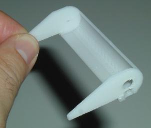
I took many pictures of the 3D printed model of TinyProjector prototype 3 and mirror (Figure 4; see also Figure 49 and Figure 50).
|
|
|
|
|
|
|
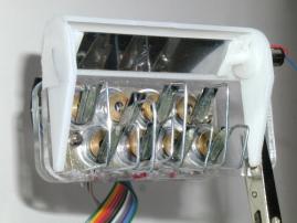
Figure 52: Add-on and prototype 2 laser holder put together |
|
March 28, 2002
I started using at 16F877 PIC: I wrote software that has patterns for all characters, digits, and many special characters. However, this program is too big even for the 16F877. Vadim suggests using the internal EEPROM memory for the constants. The program with the characters only fits into the chip, though.
I asked Chris for more laser diodes. I also emailed Lumex for sample laser diodes (5.6mm, 20 pieces, usually $5.37).
March 29, 2002
I figured out how to program to the internal EEPROM of the 16F877.
I tested several electronics schematics design programs; best is probably still Protel.
I ordered 30 cheap key chain laser pointers.
I did some Web searching about the new Honeywell diodes
http://content.honeywell.com/vcsel/pdf/sv3644-001.pdf
and why they are different from, e.g., Lumex ones
http://www.lumex.com/pls/lumex/subproduct_galary?iproduct_id=1000901
|
|
|
|
Figure 53: Lumex diode (on the left side of both pictures, golden rim) compared to the Honeywell VCSEL diode (on the right side of the pictures, longer legs) |
|
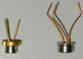
Main difference is the beam divergence: Lumex has 9 (vertical) to 35 (horizontal) degrees, similar to my key chain lasers. The new Honeywell VCSEL have more like 10-15 degrees and is oval, which means the lens can be smaller and closer. But they are also less bright: 1.5mW vs. 5mW (Figure 53).
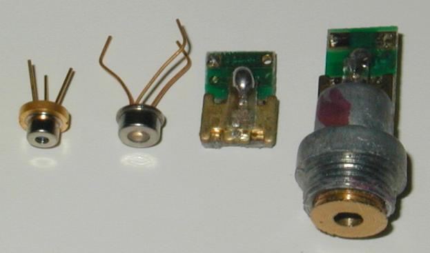
With these numbers in mind, I was starting to wonder about the beam angle (without lens) of my current old laser diodes, the “flat” ones, salvaged from the laser pointers (see Figure 54):
|
|
|
Figure 54: These are the types of laser diodes that I am using: Lumex (far left), Honeywell VCSEL (left), cheap key chain laser pointer diode (right), same with lens holder assembly (far right) |
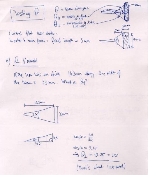
Measurements of my old (flat) laser diodes show that if its beam hits a surface 142mm away, the width is 23mm. This results in a beam angle (Theta parallel, θ║) of about 10 degrees (Figure 55):
|
|
|
Figure 55: Calculation of Theta Parallel for my “flat” laser diode |
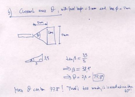
Then I calculated the maximum angle of the laser diode beam if a 7mm diameter lens is put 5mm away (which is the case in the key chain laser pointers): it is about 78 degrees (Figure 56):
|
|
|
Figure 56: Maximum Theta used for a 7mm lens at a distance of 5mm |
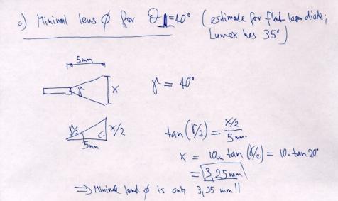
However, since I was thinking about using the small Lumex diodes that have a maximum theta of 35 degrees, I realized that the lenses could actually be much smaller in diameter than the 7mm-diameter lenses that I am using right now.
This is important
since the lens diameter dictates the overall length of a laser array. The
smaller the lenses, the smaller the projector! It turns out that a lens for a
diode with a maximum theta of 40 degrees needs only a diameter of 3.25mm! (Figure 57) This is very good news.
|
|
|
Figure 57: Minimum lens diameter for theta of 40 degrees, with lens focal length of 5mm |
March 30, 2002
TinyProjector specifications for the next prototype, and proposed solutions:
|
Specification |
Technical solution |
|
Mirror rotating as fast as possible |
Direct drive |
|
Low friction mirror |
Ball bearings; two motors, left and right |
|
Small form factor |
Small motor; parallel motor with worm gear |
|
Quiet |
No gears, or V-belt; ball bearings |
|
Mirror low mass |
Single mirror |
|
Mirror stable (torque resistant) |
Single axle (carbon fiber), mirror glued to axle; or three mirror surfaces |
|
Mirror mass symmetric |
No axle for single mirror, three mirror surfaces. |
Ball bearings: http://db.rmb-group.com/b/rmb.taf?_function=detail&_UserReference=E33AB9720CA891723CA5FC00
More design ideas:
- Put the motor inside a three-surface mirror triangle; and the batteries too?
- Use compressed air to drive the mirror?
April 2002, 1st – 21st
April 1, 2002
I made a 3D model of TinyProjector prototype 4: 8 Lumex diodes (5.6mm diameter) and 8 mirrors (7mm diameter), as well as a double-mirror (two stainless steel plates, 2mm rod) (Figure 58).
|
|
|
Figure 58: Design for TinyProjector prototype 4 with an array of 8 lenses, 8 Lumex diodes, and a two-plate mirror |
If the beam that comes out of the lens has full diameter of the lens (7mm), then in order to paint an angle of 75 degrees, the mirror only turns only for 37 degrees (see Figure 59)! That is very little. Perhaps I should use a 1mm rod, steel or carbon fiber? Perhaps the beam that comes out of the lens does not have full 7mm diameter?
|
|
|
|
|
Figure 59: Projection angle and mirror angle |
April 2, 2002
I ordered 30 very cheap key chain laser pointers on eBay, and got confirmation that they were shipped.
Furthermore, I ordered 10 Lumex low-cost laser diodes from Digikey (Figure 60)
http://www.lumex.com/pls/lumex/subproduct_galary?iproduct_id=1000901
|
|
Figure 60: Lumex laser diode |
I made 3D model of mirror holders (TinyProjector3_holders.3dm) (Figure 61), prototype 4.
|
|
|
Figure 61: TinyProjector prototype 4 lens and diode holders |
Made second rotating test mirror, with two stainless steel pieces (1/2inch x 55mm), 1/16th inch steel rod, and balsa pieces as distance holders; glued everything together with 5-minute Epoxy resin: result looks promising, very torque resistant, no "wobble".
Double mirror with 1/16th rod is rather bulky, I should use a 1mm rod (I have a carbon fiber rod, very light). I might need ball bearings for that; Homefly David Lewis has for $4:
http://www.homefly.com/bearings.htm
Perhaps use a 1.5mm rod, and Sky Hooks & Rigging ball bearings, for $5 each
http://www.mentornet.org/parts.htm#Bearings
Or then from WES, they have many different kinds:
http://www.WES-Technik.de/English/access.htm
High quality "micro ball bearings" 1mm bore seem to be very expensive, otherwise: e.g., NTN:
http://www.ntnamerica.com/products/Micro_Ball_Bearings.htm
http://www.ntnamerica.com/cgi-bin/NTNSRCH.DLL?SEARCHTYPE=BROWSELIST&CL_PartNo=681&CTYPECODE=RBMBB
http://www.bearingquotes.com/bearingquotes/dbinfo.asp?key=353948&Product=B
(NTN 681 is $61!)
Replaced a diode from prototype 2, adjusted the mirrors again (was a long process!)
I disposed of all the empty key chain laser pointer boxes (kept a few), recycling the batteries. There are only about 5 lasers left, of which only one is from the 30-laser batch. The other 4 are different (silver casing instead of gold). I also recycled 10 lenses (rest of the lenses are still around).
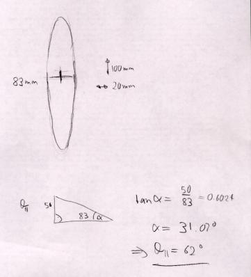
I made beam divergence measurements of current (flat) laser diode: at a distance of 83mm, the footprint is ca. 100mm tall and 20mm wide. Theta parallel is big, about 62 degrees! Theta perpendicular is about 14 degrees (that's what I expected) (Figure 62).
|
|
|
|
Figure 62: Theta parallel and perpendicular |
|
Did some testing about what the diameter of the lens has to be: sanded a 7mm diameter lens on two sides by 1mm each, so overall width is now only 5mm (Figure 63).
|
|
Figure 63: On the left side an original lens, as salvaged from a key chain laser pointer, diameter 7mm. On the right, a modified lens with sides sanded down to an overall width of 5mm. |
Optically, the outer 1mm rim does not seem to be necessary, so the modified lens worked just fine with my Lumex laser diodes. Since they have a diameter of 5.6mm, they could be aligned back to back, minimizing the overall size of the projector! Hover, the problem with such a construction would be that the diodes could touch each other, and could be difficult to align (Figure 64).
|
|
|
Figure 64: Eight-lens array, where each lens (diameter 7mm) is trimmed on two sides by 1mm, allowing to pack the lenses very close to each other, reducing overall width of the lens array from 56mm to 40mm!
|
It looks like the actual laser beam has a diameter of about 3mm when it exits the lens. The hole of the piece right in front of the lens of the key chain laser pointers has a diameter of 3mm as well. This means that the width of the mirror can be reduced, too.
I fixed several bugs in new_choic.c code (Figure 65): I did not include the right header file, 16f84a.h; counting backwards per character did not work; spacing between characters was not there.
Everything works now as expected. It can receive characters A through F and O, and displays 12 of them left-right and 12 right-left, and then waits again. Probably should use gets() function: gets a string, which ends with "enter" on the terminal.
|
#include <16F84a.h> #fuses HS,NOWDT,NOPROTECT,PUT #use Delay(Clock=10000000)
#use fast_io(A) #use fast_io(B)
#use RS232(Baud=9600,xmit=PIN_A0,Rcv=PIN_A3,INVERT)
#byte PORTA = 5 #byte PORTB = 6
#define SERVO PIN_A2
char char1; int i; int s; int forw;
byte _A[5] = { 0b00000001, 0b11101110, 0b11101110, 0b11101110, 0b00000001 };
byte _B[5] = { 0b00000000, 0b01110110, 0b01110110, 0b01110110, 0b10001001 };
byte _C[5] = { 0b10000001, 0b01111110, 0b01111110, 0b01111110, 0b10111101 };
byte _D[5] = { 0b00000000, 0b01111110, 0b01111110, 0b01111110, 0b10000001 };
byte _E[5] = { 0b00000000, 0b01110110, 0b01110110, 0b01110110, 0b01111110 };
byte _F[5] = { 0b00000000, 0b11110110, 0b11110110, 0b11110110, 0b11111110 };
byte _L[5] = { 0b00000000, 0b01111111, 0b01111111, 0b01111111, 0b01111111 };
byte _O[5] = { 0b10000001, 0b01111110, 0b01111110, 0b01111110, 0b10000001};
void project3(byte the_character[5], int the_line) {
PORTB = the_character[the_line - 1]; delay_us(1300); PORTB = 0xFF; delay_us(1000); }
void project2(char c, int line_number) {
switch(c){ case 'A': project3(_A,line_number); break; case 'B': project3(_B,line_number); break; case 'C': project3(_C,line_number); break; case 'D': project3(_D,line_number); break; case 'E': project3(_E,line_number); break; case 'F': project3(_F,line_number); break; case 'L': project3(_L,line_number); break; case 'O': project3(_O,line_number); break; default: project3(_O,line_number); }
}
void project1(char the_char, int forward) { int v;
if (forward==1) { // puts("forward"); // putc(v);
for (v=1; v<=5; v++) { project2(the_char, v); delay_us(1300); } }else{ for (v=5; v>=1; v--) { // puts("backward"); // putc(v);
project2(the_char, v); delay_us(1300); } } }
main() { set_tris_a(0b00001000); set_tris_b(0b00000000);
while(1) {
char1 = getc(); //delay_ms(200); putc(char1); // after 0.2 sec echo it
//for (s=0; s<=3; s++) { // got a character! // PORTB = 0b00000000; // delay_ms(50); // PORTB = 0xFF; // delay_ms(50); //}
for (forw=1; forw<=2; forw++) {
for (i=0; i<12; i++) {
OUTPUT_HIGH(SERVO); if (forw==1){ delay_us(1900); }else{ delay_us(1000); }
OUTPUT_LOW(SERVO);
if (forw==1) { delay_ms(2); }else{ delay_ms(3); }
// puts("--Projecting character"); // putc(char1);
project1(char1,forw);
delay_us(1300);
} // end of loop through 12 chars } // end of forw/backw loop } // end of whil } // end of main
|
|
Figure 65: Final C code for TinyProjector prototype 2 |
April 3, 2002
I scanned the drawings of the schematics and the theta calculations, and cleaned them up (see Figure 55, Figure 56, Figure 57).
I had long talk with Gerardo (gvallejo@media.mit.edu): he has a PIC background and could help me later on with PIC problems. Cool!
April 17, 2002
I did the 3D design of new casing with 1mm rod (TinyProjector prototype 4). The motor is now connected with a V-belt, for two reasons: first, a small pager motor is probably not strong enough to drive the mirror directly, Second, the overall size of the projector can be reduced if the motor is parallel to the diode/lens array rather than sticking out on the side of it.
Furthermore, the Lumex diodes are not mounted directly onto a holder with holes, but are stuck into a back wall with both feet. Reason is that they can be adjusted easily in all dimensions: left/right by bending, back/forth by inserting them more or less into the back wall (Figure 66).
|
|
|
Figure 66: Casing of prototype 4 with smaller mirror axle and V-belt |
April 18, 2002
New mirrors: it is difficult to find exact dimension stainless steel strips, 10mm wide and 0.25mm (0.01 inch) thick. Eric suggests the sheering machine of the MIT Student workshop in the Cyclotron building. The guy in charge is Fred:
http://web.mit.edu/edgerton/shop.html
Of course a good water jet cutter would also do it, or an Exacto knife.
April 19, 2002
V-belt: I should use an O-ring! To figure out the size, go to http://www.sealseastern.com/OringRodSeal.asp
E.g. "DASH 014" is the O-ring for a 1/2-inch rod, and the belt has a diameter of 0.07 inches.
The actual rings I could get from MIT Central Machine, E34 basement.
I made beam divergence measurements of Lumex laser diode: at a distance of 88 mm, the footprint is ca. 90 mm tall and 30 mm wide:
- Theta parallel is about 60 degrees (62 degrees for key chain laser diode)
- Theta perpendicular is about 21 degrees (14 degrees for key chain laser diode)
More information I found out about the Lumex diodes:
- Middle pin is positive, and only one of the outside pins is negative.
- Doesn’t run on the two old lithium batteries (2.7V). It needs exactly 2.2V. I also think I killed one by having applied a too high voltage.
- Do I need a DC-DC converter or something similar?
- The focal length is 5mm (inner distance between topmost part of diode and lens)
April 2002, 22nd – 30th
April 22, 2002
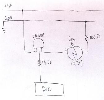
I met with Vadim about a voltage regulator for the laser diode and the motor. For the laser diode, I just need a resistor; Vadim estimates between 10 and 100 Ohm (Figure 67).
- Nominal (35mA): 4.5V/0.035A = 130 Ohm
- Max (45mA): 4.5V/0.045A = 100 Ohm
|
|
|
Figure 67: Sketch schematic for reducing the 4.5V to 2.2V of the Lumex laser diode |
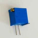
To find out the right resistance, he suggests using a potentiometer and then start from its highest resistance to low until the diode lights up, and then measure the resistance of the potentiometer.
As a potentiometer, I used a Bourns 3299-102 (1kOhm) (http://www.bourns.com/pdf/3299.pdf) (Figure 68)
|
|
Figure 68: Bourns 3299-102 potentiometer |
My first Lumex laser diode seemed to be doing fine with 60 Ohm, but then died suddenly. For the next diode, I stopped at 100 Ohm, and it seems bright enough.
I measured the focal length again: it is pretty much 5mm.
For the motor, I will probably need a Maxim 825:
http://pdfserv.maxim-ic.com/arpdf/MAX823-MAX825.pdf
[It turned out later that I do not need any specific op amp for the motor.]
I set up the PIC 16F877 on a new breadboard
I unsoldered IR LED/photodiode from the MS Trekker mouse (with the solder "sucker" device, thanks Natalia (nmarmas@media.mit.edu), and set up LED and IR LED/photodiode on the breadboard.
I killed first IR LED from the computer mouse by not using a resistor. Looked for replacement: is it this one?
http://www.fairchildsemi.com/ds/QE/QEE213.pdf
Installed a 300 Ohm resistor for the IR diode, a 100 Ohm resistor for the test LED, and will use another 100 Ohm resistor for the laser diode.
April 23, 2002
I debugged the 16F877 hardware:
- Replaced the ceramic oscillator with a 4MHz version (my PIC is only 4MHZ), thanks to Vadim.
- Added power switch, and removed the obsolete second power supply/ground connections at the PIC.
- Code to just blink an LED didn't work, or only part of the time: it looked like a bad circuit connector. However, I just had to ground pin B3, then it was OK. This pin seemed to act like an antenna, very high impedance—although it was set as an output. Gerardo says that it was probably picking up electromagnetic radiation. Eventually, it worked.
- Photodiode/infrared LED part did not work. Have to test if voltage indeed goes up and down, and then if manually setting C0 pin high/low works.
April 24, 2002
I made the photodiode and IR LED work. Software and hardware were OK: the photodiode gives about 5.1V when the LED shines, and when shaded less than 1.5V, and that’s where the PIC switches.
The problem was only that my desk lamp actually emits IR light, so it was not possible to shade the photodiode at all! Further, normal white paper or foam or Post It’s seem to be translucent for IR light: even white plastic gears do not shade enough. It has to be either metal (I tried the stainless steel strips), or black colored tape (on a business card).
The IR seems to be very strong (or the photodiode very sensitive), so the hole that lets light through can be very small. Currently, I use a slit of about half a millimeter width in the business card covered with black tape.
I could not find out where the photodiode is most sensitive (there are actually two diodes in this element): the whole surface of the photodiode has to be covered so that it goes below 1.5V (which is when the PIC decides it is LOW).
April 26, 2002
For the gearbox (V-belt, pulleys), I found LEGO Technic gear that might help: pulleys, rubber belts (probably better than O-rings!), axles, gears, etc. (Figure 69)
|
|
|
|
|
Figure 69: Rubber belts and pulleys from LEGO would fit almost perfectly |
||
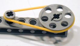
Two different LEGO bars work almost perfectly: in one of them (Figure 70), the diode can slide slightly horizontally, which would allow for alignment. However, the lens would be a little too close to the diode, so in order to focus it, it had to be raised by a fraction of a millimeter (with very thin cardboard). That's not very precise.
|
|
|
|
Figure 70: Lego part that almost perfectly fulfilled the specifications for a lens/laser diode holder |
|
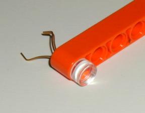
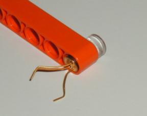
In order to fit gears and pulleys on my 2/32-inch and 1mm axle, I drilled holes in LEGO axles (Figure 71)—manually, without drill! I still need a 1mm drill bit (did it with the 1/32 bit I got from Brygg: also not long enough): the holes are good, but not completely centered. I should do that with a mounted drill. The hand drills I saw cannot take 1mm drill bits.
|
|
|
|
Figure 71: Lego pulleys with very short axles with manually drilled holes for 1.6mm steel axle (left) and 1mm carbon fiber axle (right) |
|
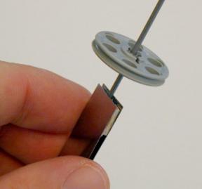
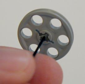
I did many tests with different kinds of gears and 1.5 - 4.5V and the medium 10mm Ballooncraft motor (Mabuchi MV2A, http://www.toytx.com/1015vmic.html): normal gears, bevel gears, and pulleys/rubber belt. The last one is the best because it is the most quiet, and the wheels do not have to be aligned perfectly (and it is difficult to align them perfectly!) With 1.5V, it runs very quietly. However, the distance has to be exactly right: if the motor is too far, the tension is too big; if it is too close, the belt is too loose and "wobbles". That could become tricky.
Since the Lego holders were not exact enough, I designed a new casing, just for the diodes and lenses (casing1.3dm) (Figure 72). This is going to be TinyProjector prototype 5.
|
|
Figure 72: First casing for diodes and lenses: front side for lenses (top), back side for laser diodes (bottom) |
|
|
I 3D printed this design, which took only 27 minutes, since there was very little support material necessary (Figure 73).
The holes for the diodes are perfect (3.7mm diameter), but the holes for the lenses are a bit too tight (7mm). Also, it will be difficult to put them in there because in order to press one in, the other basically becomes loose, because the upper part of the holder is a bit flexible. Being flexible is good, but not for all lenses at the same time.
|
|
|
|
|
Figure 73: 3D printed first casing, with a single lens and a single Lumex laser diode |
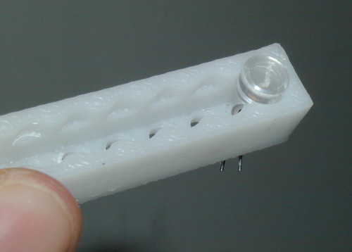
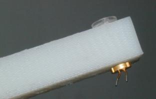
April 28, 2002
I made a new mirror holding assembly (Rhino, and then 3D printed), three versions:
Version 1 (Figure 74, Figure 75):
Lens holes 7.00mm diameter, slit on the side: good because the lenses can be snapped in. Not so good because whenever one lens is moved, all the lenses are unlocked, move, and even fall out) (casing1.3dm)
|
|
Figure 74: Lens holder with side slit |
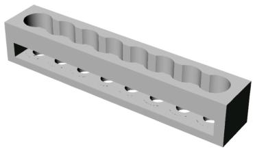
|
|
Figure 75: 3D printed lens holder with side slit
|
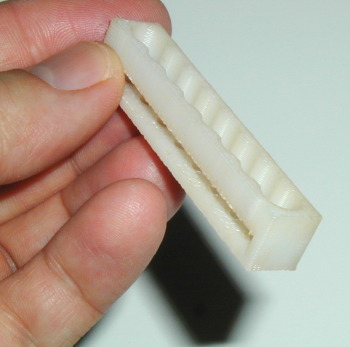
Version 2 (Figure 76, Figure 77):
Holes 7.20mm, 2mm deep, no slit. Lenses still too loose and keep falling out, so I designed and printed the lid, which should snap on top of the casing, holding down the lenses. Lid is not precise enough, though (casing2.3dm and casing_lid.3dm).
|
|
Figure 76: Holder with clip; lenses are inserted in the lower part (top right, and yellow part) and rest on ridges that guarantee the right distance to the laser diodes. The lenses are locked from top with a clip (top left, and purple part). Laser diodes are inserted from below (bottom). |
|
|
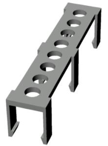
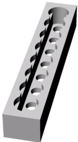
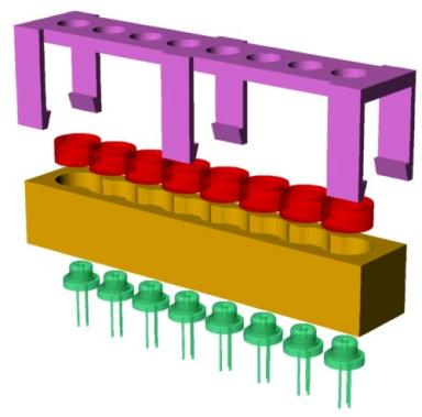
|
|
|
|
Figure 77: 3D printout of the clip and holder design. Did not work at all, since the legs of the clip were built up vertically, so they consisted of many slices of small size. In addition, the tips of the six legs were overhanging, so the 3D printer had to build up a considerable amount of support material around the legs, which is always problematic since the boundaries are not that precise. |
|
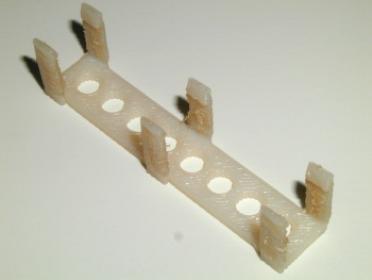
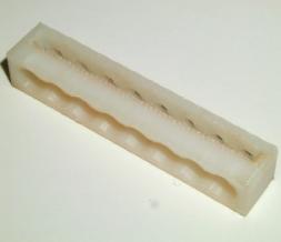
Version 3 (see Figure 78, Figure 79, Figure 80):
Lens holes 7.10mm diameter, 3mm deep, and no slit. Lenses fit nicely now, and are even with the casing outside. No need for a lid, a simple clear transparent Scotch tape is good enough. Focal length seems to be optimal (5mm), the laser diode has to be pulled back only a fraction of a millimeter to get it in focus (casing3.3dm).
|
|
Figure 78: Final holder version of prototype 5. Since the lenses snap into the holder, they just have to be secured lightly with transparent scotch tape.
|
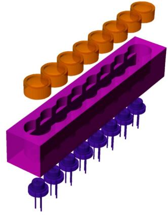
|
|
|
Figure 79: Front view of holder version three (prototype 5), with lenses and laser diodes mounted and connected. The lenses are held down only by a transparent Scotch tape
|
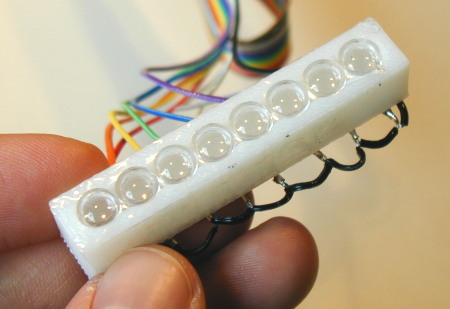
|
|
|
Figure 80: Back view of holder version three (prototype 5). The black wires connect ground between the laser diodes
|
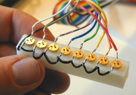
April 29, 2002
I made drawings and calculations of left-right sweeping mirror assembly for the new casing: a rotating disc is mounted directly on a small pager motor (Figure 81, Figure 82).
|
|
|
Figure 81: Sweeping mirror assembly sketch with projection angle calculations |
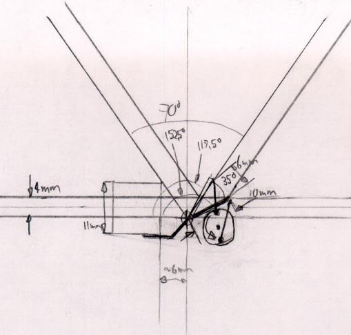
|
|
|
|
Figure 82: More sweeping mirror assembly sketches |
|
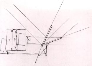
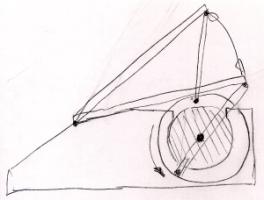
|
|
|
Figure 83: Illustrating the angles of a sweeping assembly with a lens holder |
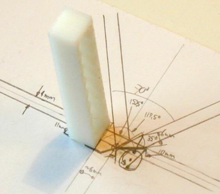
I assembled a holder prototype (see also Figure 87), with a 13mm-wide mirror: the small pager motor can turn it only with 3V and 4.5V (1.5V not strong enough), and it is rather loud. Mechanically, it is much simpler than the rotating mirror, so perhaps I keep this assembly in case I can't make the other one.
April 30, 2002
I tried to buy 1mm and 1.5mm rods from MIT Central Machine and Pearl Arts and Craft store. None of them had, but I bought a series of rods and tubes, both steel and brass.
http://web.mit.edu/cmshop/mshop.html
Eventually, I found a coated steel wire that has a diameter of 1.2mm (with coat), and about 0.9mm (without coat). The plastic coat is very useful to link the 1mm axle of the small pager motor. If a scotch tape is wrapped around the uncoated wire, the diameter is pretty much 1mm!
I made a double-sided mirror with the 0.9mm rod, two mirrors (13mmx60mm), and 5-minute epoxy resin (Figure 84).
|
|
Figure 84: Double-sided mirror made of two half-inch strips of stainless steel and a 0.9mm axle. The spacers on all four corners are made of balsa wood. This construction is very rigid, compared to a single strip without axle! |
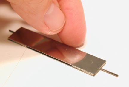
I made a crude assembly out of three hard wood pieces (Figure 85): one for the ball bearings (bore 1mm, outer diameter 3mm), with a 2.45mm hole, the other for the small pager motor, with a 6mm hole. The holes were drilled in the machine shop, on the big vertical drill. This was the first version of TinyProjector prototype 6.
|
|
Figure 85: Hardwood holder mock-up for prototype 6, with a 6mm motor and 3mm ball bearings. Note that the connection between the motor axle and mirror axle consists solely of some leftover plastic coating (white) that covered the axle originally. This simple connection seems to be sufficient. |
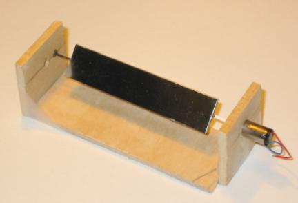
The mirror assembly works well: it is noisy at 3V, but very quiet at 1.5V. Looks like it could work that way!
May 2002, 1st – 2nd
May 1, 2002
I drew a sketch of how the rotating mirror assembly (with disk for photodiode/IR LED) might look like (Figure 86).
|
|
Figure 86: Rotating mirror assembly with photodiode/IR LED
|
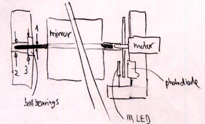
I tested the rotating mirror assembly with an always-on laser diode: it works, draws a nice thin line on the wall, but the brightness of the Lumex laser diode is very low, probably too low; the same result with a key chain laser pointer.
Thinking more about that, I realized that there is a fundamental problem with having a 360-degrees continuously rotating mirror. If the projection angle is 60 degrees, then the mirror has to rotate only 30 degrees to create this projection. In other words: the laser diode is turned off during 330 degrees of a full rotation, or during 92% of the time! After the projection, the laser has to wait until the mirror rotates for another 330 degrees, and only then can light up during the last 30 degrees in order to create a 60-degrees projection.
This has a very important consequence: Such a low duty cycle requires a very high power laser diode. E.g., a laser diode that can project during 100% of the time creates a 12.5 times brighter projection than a laser diode with a duty cycle of 8% (or dead time of 92%). And this is exactly the problem with patent 6222459, mentioned earlier (see Figure 36). Theoretically, it works, but it is terribly inefficient!
This numbers get a bit better if the mirror has two usable surfaces, e.g., front and back of the same plane. With two surfaces and a projection angle of 60 degrees, the two-sided mirror uses 2x 30 degrees or a full rotation for projection, but is still unusable during 300 degrees of the rotation, or during 83% of the time. Such a projection would be still almost 6 times less bright than a construction that allows the laser diodes to run at a 100% duty cycle.
There are two constructions that allow a 100% duty cycle for a 60-degrees projection:
- 12 mirrors mounted on the outside of a tube (see also the calculations of Table 1)
- Single mirror with a left-right sweeping motion
Solution 1 is unacceptable because such a mirror assembly would get very bulky (see Figure 17, a picture of a 8-faced mirror). The reason is that the width of each mirror cannot be reduced beyond the diameter of the laser beam, which is typically around 3mm. Even worse, depending on the angle with which the laser beam hits the mirror, each of the 12 mirrors has to be remarkably wider than the diameter of the laser beam itself.
Solution 2 does not have this disadvantage, since there is only one mirror surface necessary, but it suffers from another disadvantage: vibration. Minimizing the mass of the mirror, however, will minimize vibration.
For all these reasons (and since I do not have access to super bright laser diodes), I continued working on a back-and-forth sweeping mirror construction (see also Figure 81, Figure 82, Figure 83).
In a first version, TinyProjector prototype 7, I used a 6mm pager motor (Mabuchi J20WA) with a single-arm plastic crank (Styrene) mounted on the axle (Figure 87). Unfortunately, with 1.5V current, the motor was not able to swing the mirror (1/2 inch stainless steel strip) at an acceptable speed. The assembly works with 3V, but gets noisy and, more importantly, the motor gets very hot.
|
|
Figure 87: Prototype 7: back-and-forth sweeping mirror construction with small 6mm pager motor. (On this picture, it is already shown with IR LED and photodiode as well as mock-up lens and laser diode holder, mounted on the right arm of the gripper.) |
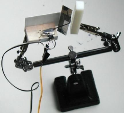
|
|
Figure 88: Detail of prototype 7, back-and-forth sweeping mirror construction: the swiveling arm that also drives the mirror interrupts the IR light between LED and photodiode. |
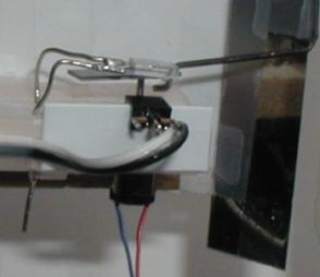
Since the 6mm motor did not seem to be strong enough, I made another sweeping mirror assembly (TinyProjector prototype 8), with the bigger pager motor, a Mabuchi MV2A.
|
|
Figure 89: Motor Mabuchi MV2A, diameter 11mm |
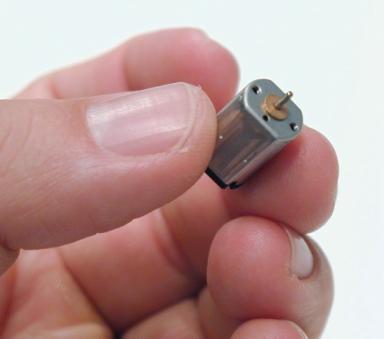
|
|
Figure 90: Size comparison between small pager motor (Mabuchi J20WA, right) and bigger pager motor (Mabuchi MV2A, right) |
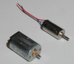
In the Ballooncraft™ where the Mabuchi J20WA comes from, it works with 1.5V (nominal voltage). At this current level, the noise of TinyProjector prototype 8 is acceptable, but the vibrations are rather strong, as expected. Nevertheless, the big advantage is that the laser beam can work with a duty cycle of 100%! Even if I only use one direction of the sweeping movement, the laser is on at least on 50% of the time. The hinges, made of Scotch tape, wear out quickly, though. This is understandable with the high sweep rate. Because the hinges fail gradually, the movement from left to right and the one from right to left do not really overlap. Better hinges will be necessary.
|
|
Figure 91: TinyProjector prototype 8: similar sweeping mirror assembly, with bigger motor Mabuchi MV2A, and black Styrene servo arm
|
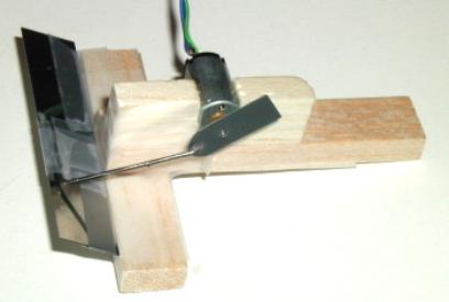
Because of the severe vibration, Eric suggested again looking into the multi-sided mirror option. He suggested using the hexagonal brass tube that I happened to have lying around, but it is not a good enough mirror. The square aluminum tube (1/4 inch) seemed to be another option, so we went downstairs polishing it. The ultimate solution would be a square or hex stainless steel tube/rod that is polished to mirror quality. Eric says that MIT Central Machine could do that for me, and we looked it up in McMaster-Carr (searched for "hex").
I disassembled a key chain laser pointer of the new batch to harvest the 8th mirror that was missing. It was very difficult because the screw that holds the lens is now made of plastic, and cannot easily be unscrewed. I ended up cutting the casing up from the other side (very tricky). I hope this is the only laser pointer of the new batch that is so difficult to open. The mirrors are now fixed with two narrow Scotch tapes, covering about 1mm on each side of the lens.
On the breadboard, I set up the laser diode with the transistor, after consulting with Vadim about if it is OK. He said that the 100-Ohm resistor might be too much because the transistor itself acts as a resistor. First, it didn't work at all, until I realize that the 2N3906 transistor makes the laser light up inverse to the already connected LED! (I had to write a short program that just flashes all C port pins to find that out.) Then I played around with the potentiometer of the laser diode, and I must have damaged the diode: it got worse and worse. Then I tried the third laser diode, and the 100-Ohm resistor was actually exactly the right resistance.
Because I have only 8 Lumex diodes left, I ordered 8 more from Digikey. It would be too bad if I would run out of diodes in the next few days!
May 2, 2002
I added the photodiode to the larger sweeping mirror assembly, to make the system finally closed-loop. The IR light is not necessary; daylight seems to be enough to trigger it. The "servo arm" that holds the pushrod (on one side) and covers the photodiode (on the other, longer side) is made out of black Styrene. (It is thinner than the white ABS, although the packaging says the Styrene strip is 0.8mm thick and the ABS 0.5mm. That must be a mistake.) Perhaps I should use balsa, or thicker and more stable ABS and paint it black (the white ABS does not block the IR light for the diode!)
I wrote some code that starts a blinking sequence when the black plastic part covers the receptor, but it is hard to find out if it does the right thing without actually seeing the laser blink in the mirror. (I just checked with the attached LED.)
I made a presentation for Chris, showing him all current prototypes, and describing the current problems: rotating mirror is best because of low vibration and energy consumption, but bad for light efficiency (laser line only very thin). Sweeping mirror is more efficient but vibrates a lot and is noisy. I will probably follow up on both construction designs.
I talked to Willy a lot: he showed me his optical galvanic scanner (probably an open loop galvanometer). It is heavy and does only a very small angle, but eventually that is probably the right way to go. There will be a trade-off between mirror size (his current mirror is very small), torque, angle, power consumption, etc. Note that the latest version of TinyProjector is actually a closed-loop system!
Galvanic scanners:
- http://www.gsilumonics.com/
- http://www.gsilumonics.com/product_data_sheets/295.html
- http://www.gsilumonics.com/opticalscanning/galvanometer_selection.html
- http://www.wmrc.com/businessbriefing/pdf/photonics2001/technology/GSI_Lumonics.pdf
Theory of galvanic scanners:
- http://laser.shows.org/theoryof.htm
- http://laser.shows.org/scanners.htm
- http://www.laserfx.com/Works/Works3S.html
Although I was working on a left-right sweeping mirror assembly (TinyProjector prototype 7 and prototype 8), I kept on working on a continuously rotating mirror assembly. I designed and 3D printed a holder for the rotating mirror, a simple U shaped piece (Figure 92). This is following up on the wooden holder made earlier (Figure 85), which was named TinyProjector prototype 6:
|
|
Figure 92: U piece with holes for prototype 6
|
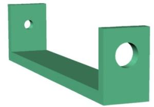
Although the 3D model looks acceptable, the 3D printer had problems with it. The side walls had to be built up vertically, so the holes for the ball bearings (3mm) and motor (6mm) had to be filled with a lot of support material. This is problematic, especially at this small size and with a vertical hole. So neither of the holes came out well, and I had to re-drill both of them manually (Figure 93).
|
|
Figure 93: 3D printout of the U piece. The holes were very imprecise and had to be redone manually (which was also not very precise). |
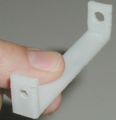
|
|
Figure 94: Miniature ball bearings with an outer diameter of 3mm, for the 0.9mm axle |
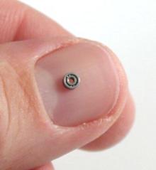
Furthermore, when I tried to insert the ball bearings (Figure 94) into the sidewall, I damaged them, because the hole was not big enough, and I applied too much axial pressure. Obviously, ball bearings of this size and type are rather sensitive to axial pressure.
Interestingly, later I found out that if the whole assembly is hold vertically, the white tube (plastic coating) that connects the motor axle to the mirror axle is rigid enough to make the mirror spin freely, without any support on the other side! I concluded that the ball bearings do not seem to be very crucial in this construction.
So I made a new U piece (U_piece2), with no holes. I drilled the holes afterwards (6mm on the drill machine, the 1mm hole manually), and it works very nicely, even without the micro ball bearings (Figure 95). It looks like the ABS (3D printed plastic) friction properties are close to nylon bushings.
|
|
|
|
|
|
|
Figure 95: 3D printed U piece (prototype 6) with rotating mirror (axle 0.9mm, 6mm pager motor, direct drive) |
|
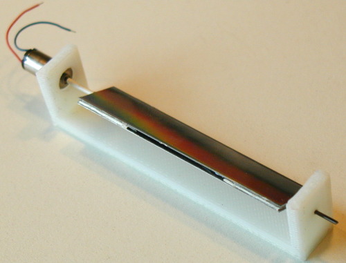
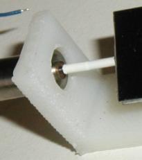
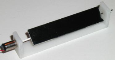
However, for reasons mentioned before, the rotating mirror seems very nice and quiet, but is nevertheless terribly inefficient. This approach turned out to be a dead end.
Therefore, I continued working on the smaller sweeping assembly (see Figure 87 and Figure 88).
After some tweaking, the smaller assembly with the 6mm motor is now working with 1.5V, and is much more quiet and has less vibration than the bigger one. I think I should go with this one. I just have to find the right hinges: they have to be very light going, and still hold longer than normal scotch tape. Perhaps using real hinges? If the hinges are not stable, the mirror wobbles (a so-called cross-axis wobble), and the lines painted by the laser are not straight, but somewhat curved. Of course the stainless steel mirrors are not optimal: probably best would be optical grade beryllium for its superior stiffness-to-weight ratio.
The correct sweeping angle of the mirror seems to be about 35 degrees: measured from the horizontal, the upper position is 80 degrees, the lower position ca. 42 degrees, which results in a 38 degrees sweep (see also Figure 82 and Figure 83). This is based on a servo arm of 4mm, pushrod length of 20mm, and the pushrod is mounted on top of the mirror. (The elevation of the top edge of the mirror is about 9mm). It is smaller than with the bigger sweeping mirror assembly, which has probably about 80 degrees. The smaller the angle, the brighter the laser painted line, the shorter the length of the laser painted line (of course). It is important to find the "sweet spot" between length of line (amount of characters that can displayed) and brightness. In this assembly, the angle of the laser should be about 0 to 10 degrees (measured from the horizontal base line).
May 2002, 3rd – 6th
May 3, 2002
I built mock-up of sweeping mirror assembly (small motor, prototype 7), mounting all elements onto a gripper with two hands (Figure 96; see also Figure 87 and Figure 88).
|
|
|
Figure 96: Smaller sweeping mirror assembly |
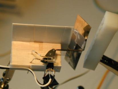
I started to tune the software, and made it work—almost.
I also made many drawings of sweeping mirror assemblies, based on the mock-up that works, taking into account the right angles for the mirror, etc. (see Figure 82)
May 4, 2002
I made a 3D model of all elements (TinyProjector_all.3dm), including the new mirror parameters, etc. This was going to be TinyProjector prototype 9.
|
|
|
|
|
Figure 97: First complete designs of prototype 9. Note that this prototype is modular: the lenses are hold by the assembly shown in Figure 79 and Figure 80. |

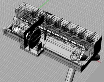
I 3D printed two versions of the frame (TinyProjector2_all_frame.3dm, TinyProjector2_all_frame_v2.3dm), see Figure 98: The first has triangle stiffeners on top of the laser array holder, which make it look big and are actually not necessary for stiffness. So the second version doesn't have them; furthermore, the element that holds the photo diode and the IR LED is thinner, and the connecting bar between motor and laser array is less high. In addition, the first version did not come out properly, probably because of inverted normals: overlapping sections of the corner of the laser array holder were omitted. They probably cancelled each other out somehow during the transformation to SLT, or within Quickslice. Was easy to fix by deleting the overlapping sections of the bricks in Rhino. I also did a Boolean union of all elements in the second version, so that the whole frame is just one element.
|
|
|
|
Figure 98: Two version of the frame for prototype 9: the first (purple left) had additional stabilizer on top of the mirror holder, which turned out to be unnecessary. The second (green right) looks a bit more elegant |
|


Then I fine tuned the mirror mock-up on the gripper: I figured out how long the delay has to be so that the blinking sequence starts a bit after the turn of the mirror: it's 16ms. This delay of course depends on the servo arm with two arms: it covers the photo diode with one arm, 180 degrees after the arm with the pushrod passes. (In the next version of the assembly, TinyProjector_all.3dm, the servo arm has just one arm: it holds the pushrod and at the same time covers the photo diode. This will change the timing, of course. But that will not be a problem, since I know the overall length of a sweep now, and will be easily able to tell where the blinking sequence starts, e.g., by adding a long blink at the beginning.) The current blinking signal is 85 dots, each 120 microseconds long, followed by at 120 microsecond pause, which means one sweep (left-right) takes abut 20ms, a complete oscillation (left-right-left) a bit more than 41ms, which means the mirror flaps with a frequency of 25Hz. Looks good, the line covers most of the "good" area of the sweep, avoiding the areas where the mirror switches the direction of the movement. However, the mirror hinge is not very stable, it wobbles, so the line is not very straight.
May 5, 2002
I started to assemble the 3D printed assembly from yesterday, the second version. I made all the holes: for the mirror hinges, for the photo diode (both manually with the tiny drill bit I got from Brygg), and for the motor (with the drill machine in the shop; was a pain, because there is not exact 6mm drill bit, and I couldn't attach the piece to the drilling machine).
I made the mirror: glued the 0.9mm wire onto the edge of a 57mm long mirror with epoxy resin, shortened the wire to 67mm. Insertion of mirror into frame works perfectly! Secured the mirror hinge with two pieces of Scotch tape, on the outside of the frame. The insertion of the photo diode works nicely too, and is at the right position (right underneath the motor axle).
Then I 3D printed the mirror handle and the servo arm, two versions, 0.5mm and 1mm thick (TinyProjector2_all_mirrorholder.3dm). Used the 1mm version (Figure 99).
|
|
|
Figure 99: Design of the mirror holder and the servo arm. It looks nice in the modeling software! |
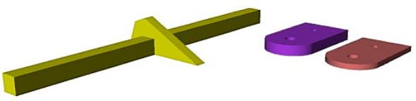
|
|
Figure 100: 3D printout of the two servo arms: on left the side the 1.0mm thick one, on the right side the 0.5mm thick one. This is definitively the limit of our current 3D printer, at least with the current print heads (T16). Basically, the piece consists of one layer of ABS traces, trying to fill the plane (not very successfully) |
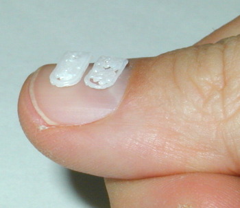
|
|
Figure 101: Close-up of the two 3D printed servo arms. The limitations of the printer are clearly visible |
Obviously, this wasn’t going to be stable and precise enough, and certainly not blocking the IR form the LED, so I cut out a servo arm manually from ABS plastic sheet.
|
|
Figure 102: ABS servo arm, with one end blackened. This was necessary since the ABS plastic did not shield the IR light of the LED well enough! |
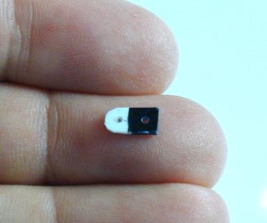
[Note that later, I will replace the 3D printed servo arm with a metal arm; the slipping servo arm was the main reason for jitter in the projection.]
I taped the mirror handle onto the mirror assembly, and made a pushrod with thin string wire (diameter 0.025 inches, 0.635mm). It works! The mirror turns light enough to be driven by the motor.
May 6, 2002
I glued the tiny mirror handle to mirror, and made a new pushrod that doesn't fall out. Works perfectly.
I soldered in the laser diodes, and to the cable band.
I assembled breadboard with all transistors and resistors, and connected the cable band.
|
|
|
Figure 103: Breadboard of TinyProjector prototype 9: there are only very few electronic elements necessary |
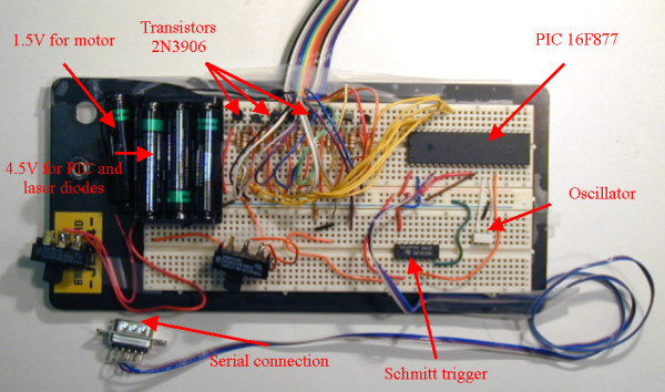
I finally fixed the bug with the B3 pin that seems to need to be grounded. It was actually a directive (in #fuses) that switches this pin on.
http://www.ccsinfo.com/faq/?32
(Gerardo suggested first another solution, writing directly do the register, but that was not necessary.)
During tuning (with resistors), I killed one laser diode. Got the 8 new laser diodes from Digikey.
Big problem: the alignment of the lasers is not good. Solutions:
- Heat the 3D printed ABS parts slightly up and adjust the lasers manually. However, the diodes might not like the hot soldering iron.
- Open up the holes (with a soldering iron?) and hot glue the diodes in there. The lasers might change position later again.
- Build another laser diode holder, where the lasers are held by the two pins, one upward, one downward (similar to the version where the diodes sit on their three legs.)
May 2002, 7th – 15th
May 7, 2002
I couldn't solve the alignment problem: the diodes are too tight, and if they would not be tight, every pull on the signal wires would de-align them. Solutions: Wrapping a cord (0.025 elastic wire) twice around the front part of the diode. Disadvantage: too difficult to align. Pull of wires would misalign the assembly.
Finally, I designed a solution that uses just two parallel, isolated, soft wires that are soldered to the laser's pins, and glued each with two holes to the 3D printed holder, with a U shaped ending (Figure 104).
Therefore, one inner side of the holder had to be made thinner, so that the wires (the U part) do not get in the way of the laser path. The connections (GND and signal) would be soldered on the other side of the U, which deflects all forces away from the wires that hold the diodes.
|
|
Figure 104: 3D design of alignment solution: double U holder for laser diodes, making them very easy to align by just bending the two isolated wires (green and red) slightly |
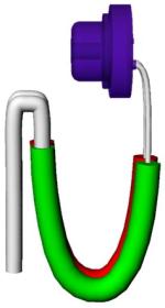
|
|
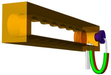
|
|
|
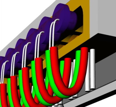
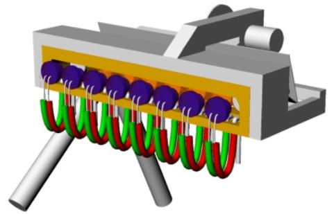
During the day, I could not print another diode holder because there was a 16-hour job on the 3D printer that started at 5pm. So I decided to experiment with an earlier version of the holder, cutting away the back of the holder.
May 8, 2002
I finally 3D printed several versions of the diode holder (Figure 105).
|
|
Figure 105: Holder with open back |
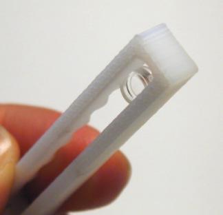
I assembled one, by drilling 32 holes manually (four for each laser: a pair for ground, and a pair for current), and inserting isolated wire from jumper wire kit, which was a pain. Epoxy glued the wires in. Connected all the GND pins with one stiff piece of wire. Aligned the laser diodes (was possible, but still took some time): the alignment is on an acceptable level now.
|
|
|
|
Figure 106: Test of laser diode holder (left), completed holder (right) |
|
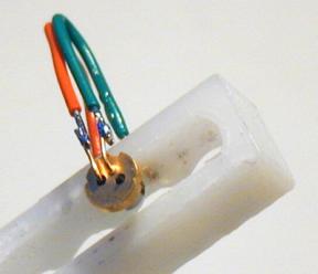
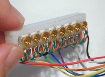
|
|
Figure 107: Laser diode holders consisting of a double U shaped isolated wire
|
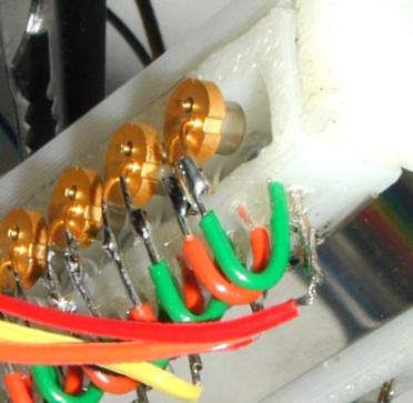
In the following, a few pictures of the completed TinyProjector prototype 9.
|
|
|
|
|
|
|
|
|
|
|
|
|
|
|
|
Figure 108: Final prototype 9 of TinyProjector |
|
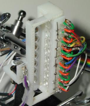
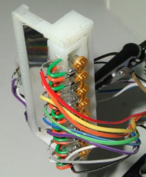
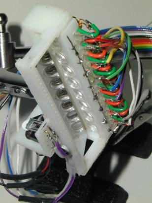
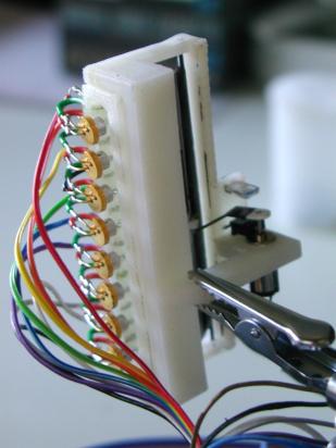
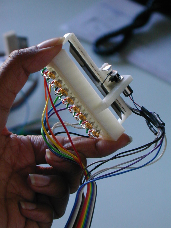
Then I wrote all software for receiving serial code, and writing single characters (A-Z, !) (Figure 109)
|
#include <16F877.h>
// File name: tiny2p2.c
// Configure PIC to use: HS clock, no Watchdog Timer, // no code protection, enable Power Up Timer
#fuses HS,NOWDT,NOPROTECT,PUT,NOLVP
// Tell compiler clock is 4MHz. This is required for delay_ms() // and for all serial I/O. These functions use software delay // loops, so the compiler needs to know the processor speed.
#use Delay(Clock=4000000)
// Declare that we'll manually establish the data direction of // each I/O pin on ports A, B, and C.
#use fast_io(A) #use fast_io(B) #use fast_io(C) #use fast_io(D)
#use RS232(Baud=9600,xmit=PIN_A0,Rcv=PIN_A3,INVERT)
// Set variable that maps to memory #byte PORTA = 5 #byte PORTB = 6 #byte PORTC = 7 #byte PORTD = 8
byte _SPACE[5] = { 0b11111111, 0b11111111, 0b11111111, 0b11111111, 0b11111111 };
byte _EXCL[5] = { 0b11111111, 0b11111111, 0b01100000, 0b11111111, 0b11111111 };
byte _A[5] = { 0b00000001, 0b11101110, 0b11101110, 0b11101110, 0b00000001 };
byte _B[5] = { 0b00000000, 0b01110110, 0b01110110, 0b01110110, 0b10001001 };
byte _C[5] = { 0b10000001, 0b01111110, 0b01111110, 0b01111110, 0b10111101 };
// ETC, ETC, all characters of the alphabet
char char1;
int i; int z; int x;
void project3(byte the_character[5], int the_line) {
PORTB = the_character[the_line]; delay_us(80); //worked: 80 PORTB = 0xFF; delay_us(60); //worked: 60 }
void project2(char c, int line_number) {
switch(c){ case 'A': project3(_A,line_number); break; case 'B': project3(_B,line_number); break; case 'C': project3(_C,line_number); break;
// ETC, ETC, again, switches to all characters of the alphabet
default: project3(_SPACE,line_number); } }
void project1(char the_char) {
int v; for (v=0; v<5; v++) { project2(the_char, v); } delay_us(500); }
main() {
// Since we've declared #use fast_io(A)(B)(C) (above), we MUST // include a call to set_tris_a/b/c() at startup.
set_tris_a(0b00001000); // A3 is input (serial) set_tris_b(0b00000000); // all Bs are outputs set_tris_c(0b00000001); // C0 is input (photodiode) set_tris_d(0b00000000); // all Ds are outputs
while(1) {
char1 = getc(); putc(char1); // echo char1
PORTB = 0x00; delay_ms(200); PORTB = 0xFF;
z=0;
while (z<40) {
if (input(PIN_C0)) { // most of the time, diode is not covered: PORTB = 0xFF; // turn lasers off }else{ // at the point where the diode is covered: delay_ms(15); for (x=0; x<8; x++) { project1(char1); } z++; } // end of diode is covered
} // end of small while
} //end of big while loop
} // end of main |
|
Figure 109: Excerpts of the PIC code that displays all characters, and receives input from the serial port (tinyp2.c) |
Later, I added some preset text lines that are triggered by sending single digits from 2-9 over the serial port to the PIC.
Then I connected the TinyProjector prototype 9 to Natalia's Palm 5, and it worked well with Pterminal and Graffiti (Figure 110).
|
|
|
Figure 110: TinyProjector prototype 9 connected to a Palm Pilot via serial cable |
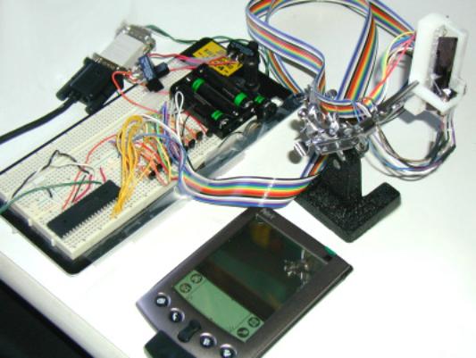
However, there was still a problem: the sensor seems to fluctuate, generating horizontal jitter in the projection. Either it is mechanical imperfections of the servo arm (tried to make it better, but was not successful), or to much stray light (built a cardboard casing around the IR and diode, but did not seem to make a difference.)
Stayed up all night to make it work! Here are the problems that came up:
- Multiple triggering of the sensor makes projection jittery (on the horizontal axis): I have to check the signal with an oscilloscope, and make it less sensitive. Perhaps with a filtering mechanism?
- I still have to figure out how to read characters from the serial port without waiting for getc. Perhaps with kbhit? http://www.ccsinfo.com/faq/?25
- The calibration is still sub optimal: where the mirror starts (the amount of delay after the sensor reports a shadow), and how wide it is (how many pixels of a given size there are)
- Make the projection less high by arranging the laser beams vertically closer to each other. Like that, the distance to the wall can be increased, and—as a consequence—the horizontal resolution: this allows for displaying more characters.
- Build a protective casing around current prototype 9
- Design and build a dedicated circuit board that contains all electronic components, possibly using surface mount PIC and transistors.
May 14, 2002
I connected the photodiode to the oscilloscope: it indeed showed a double triggering. The peaks are about 10ms apart. Furthermore, Gerardo says that the levels are very low: 1V is the max (which is strange, because I think I measured it earlier, and it gave 4.5V)
|
|
|
Figure 111: Part of the signal of the photo diode during operation of TinyProjector |
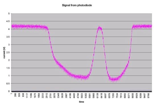
May 15, 2002
With Gerardo's help, I measured the output of the photodiode (again). On a voltmeter, it is between 1V and 4.3V. Then, we measured on an oscilloscope, and it looked similar. (The measurements yesterday were not correct; there must have been some problems with the settings.) The signal is generally high at 4.3V, and drops to approx. 1V when the servo arm passes. Actually, it has two lows, separated with a high spike. First we thought that this is causing the jittering: sometimes the PIC detects the first low, sometimes the second. However, that is not the case, because when the PIC detects the first low, it waits 15ms, and then starts with the blinking sequence that in itself lasts 9.6ms. Therefore, the PIC detects a low, and then ignores the photodiode signal for 25ms, and only then looks for a low again. At that point, the signal is high again for sure.
In order to solve the jittering problem, we inserted a Schmitt trigger (with buffer) to straighten out the signal (see screenshots, Figure 112). Although the signal looks very clean now (no slopes anymore), both the signal in the oscillator and the projection still jitter. These two might actually not be because of the same reason.
|
|
|
Figure 112: Signal of photodiode directly (top, blue line), and with the Schmitt trigger (bottom, yellow line) |
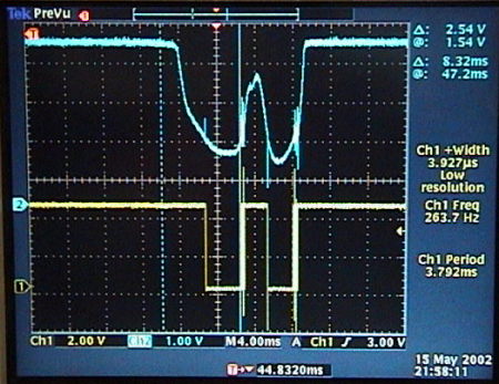
The oscillator says that the signal frequency that comes from the photodiode is between 120 and 145Hz. However, it doesn't really matter that this frequency is not constant, if the motor (rotation speed) is the reason for the jittering of the oscillator signal. Such a variation would just translate in a variable refresh rate, which is not relevant.
If the motor is the reason for the jitter in the oscilloscope signal, then it is the connection between motor and mirror that is reason for the jitter in the projection. Whenever the photodiode triggers the laser sequence, the mirror has to be at the same place. That does not seem to be the case: it's probably the connection (hole) between the servo arm and the pushrod that wears out more and more. One solution would be to glue in a ball bearing instead of a plain hole, another one could be to use thicker material or harder material, like aluminum as a servo arm.
Natalia gave me an iDen phone with a little Java application that sends characters to the serial port (Figure 113).
|
|
|
Figure 113: TinyProjector prototype 9 connected to a iDen cellphone via serial cable |
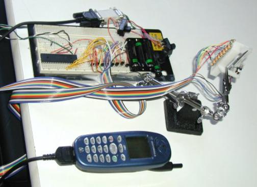
May 2002, 16th – 31st
May 16, 2002
I wrote new PIC code that intercepts serial input even during projection, using the KBHIT function (tp2_cont.c) (Figure 114). It works nicely with the Java iDen phone. I also fixed several other bugs: messed up character templates; detects now both lowercase and uppercase single characters; preset lines are limited to 8 characters, etc.
|
#include <16F877.h>
// File name: tp2_cont.c
// Configure PIC to use: HS clock, no Watchdog Timer, // no code protection, enable Power Up Timer
#fuses HS,NOWDT,NOPROTECT,PUT,NOLVP
// Tell compiler clock is 4MHz. This is required for delay_ms() // and for all serial I/O. These functions use software delay // loops, so the compiler needs to know the processor speed.
#use Delay(Clock=4000000)
// Declare that we'll manually establish the data direction of // each I/O pin on ports A, B, and C.
#use fast_io(A) #use fast_io(B) #use fast_io(C) #use fast_io(D)
#use RS232(Baud=9600,xmit=PIN_A0,Rcv=PIN_A3,INVERT)
// Set variable that maps to memory #byte PORTA = 5 #byte PORTB = 6 #byte PORTC = 7 #byte PORTD = 8
#define MAX_CHAR 8 #define DELAY_TI 16500
byte _ALL[5] = { 0b00000000, 0b00000000, 0b00000000, 0b00000000, 0b00000000 };
byte _SPACE[5] = { 0b11111111, 0b11111111, 0b11111111, 0b11111111, 0b11111111 };
byte _EXCL[5] = { 0b11111111, 0b11111111, 0b01100000, 0b11111111, 0b11111111 };
byte _A[5] = { 0b00000001, 0b11101110, 0b11101110, 0b11101110, 0b00000001 };
byte _B[5] = { 0b00000000, 0b01110110, 0b01110110, 0b01110110, 0b10001001 };
byte _C[5] = { 0b10000001, 0b01111110, 0b01111110, 0b01111110, 0b10111101 };
// ETC, ETC, all character templates
char char1;
int i; int x;
void project3(byte the_character[5], int the_line) {
PORTB = the_character[the_line]; delay_us(80); PORTB = 0xFF; delay_us(60); }
void project2(char c, int line_number) {
switch(c){ case 'A': project3(_A,line_number); break; case 'a': project3(_A,line_number); break;
case 'B': project3(_B,line_number); break; case 'b': project3(_B,line_number); break;
case 'C': project3(_C,line_number); break; case 'c': project3(_C,line_number); break;
// ETC, ETC, switching statements for all characters
case ' ': project3(_SPACE,line_number); break; case '!': project3(_EXCL,line_number); break; case '9': project3(_ALL,line_number); break;
default: project3(_SPACE,line_number); } }
void project1(char the_char) { int v; for (v=0; v<5; v++) { project2(the_char, v); } delay_us(500); }
main() { // Since we've declared #use fast_io(A)(B)(C) (above), we MUST // include a call to set_tris_a/b/c() at startup.
set_tris_a(0b00001000); // A3 is input (serial) set_tris_b(0b00000000); // all Bs are outputs set_tris_c(0b00000001); // C0 is input (photodiode) set_tris_d(0b00000000); // all Ds are outputs
while(1) {
if (kbhit()) { char1 = getc(); }
switch(char1){ case '9':
if (input(PIN_C0)) { // most of the time, diode is not covered: PORTB = 0xFF; // turn lasers off }else{ // at the point where the diode is covered: delay_us(DELAY_TI);
for (x=0; x<MAX_CHAR; x++) { project1(char1); }
} // end of diode is covered
break;
case '8':
if (input(PIN_C0)) { // most of the time, diode is not covered: PORTB = 0xFF; // turn lasers off }else{ // at the point where the diode is covered: delay_us(DELAY_TI);
project1('H'); project1('E'); project1('L'); project1('L'); project1('O'); project1('!'); project1('!');
} // end of diode is covered
break;
case '7':
if (input(PIN_C0)) { // most of the time, diode is not covered: PORTB = 0xFF; // turn lasers off }else{ // at the point where the diode is covered: delay_us(DELAY_TI);
project1('W'); project1('E'); project1('L'); project1('C'); project1('O'); project1('M'); project1('E'); project1('!');
} // end of diode is covered
break;
case '6':
if (input(PIN_C0)) { // most of the time, diode is not covered: PORTB = 0xFF; // turn lasers off }else{ // at the point where the diode is covered: delay_us(DELAY_TI);
project1('M'); project1('E'); project1('D'); project1('I'); project1('A'); project1('L'); project1('A'); project1('B');
} // end of diode is covered
break;
case '5':
if (input(PIN_C0)) { // most of the time, diode is not covered: PORTB = 0xFF; // turn lasers off }else{ // at the point where the diode is covered: delay_us(DELAY_TI);
project1('T'); project1('I'); project1('N'); project1('Y'); project1('D'); project1('E'); project1('M'); project1('O');
} // end of diode is covered
break;
case '4':
if (input(PIN_C0)) { // most of the time, diode is not covered: PORTB = 0xFF; // turn lasers off }else{ // at the point where the diode is covered: delay_us(DELAY_TI);
project1('Y'); project1('O'); project1('U'); project1(' '); project1('S'); project1('U'); project1('C'); project1('K');
} // end of diode is covered
break;
case '3':
if (input(PIN_C0)) { // most of the time, diode is not covered: PORTB = 0xFF; // turn lasers off }else{ // at the point where the diode is covered: delay_us(DELAY_TI);
project1('O'); project1('H'); project1(' '); project1('Y'); project1('E'); project1('A'); project1('H'); project1('!');
} // end of diode is covered
break;
case '2':
if (input(PIN_C0)) { // most of the time, diode is not covered: PORTB = 0xFF; // turn lasers off }else{ // at the point where the diode is covered: delay_us(DELAY_TI);
project1('G'); project1('O'); project1(' '); project1('H'); project1('O'); project1('M'); project1('E'); project1('!');
} // end of diode is covered
break;
default:
if (input(PIN_C0)) { // most of the time, diode is not covered: PORTB = 0xFF; // turn lasers off }else{ // at the point where the diode is covered: delay_us(DELAY_TI);
for (x=0; x<MAX_CHAR; x++) { project1(char1); }
} // end of diode is covered
} // end of case switch
} //end of big while loop
} // end of main |
|
Figure 114: Final PIC C code for prototype 9: it intercepts serial input even during projection with the KBHIT function (tp2_cont.c). Missing in this listing are only the complete set of character templates, and the complete set of switching statements. For full code, send me email. |
I wrote another version of the PIC code that detects a drop of the photodiode pin (tp2_ger.c): it starts the blinking sequence only when there is a high pin immediately before a low pin. This was a suggestion of Gerardo. It did not make the jitter go away, but the projector misses now many cycles. I did not pursue this approach.
I made a new servo arm out of aluminum, salvaged from a square aluminum tube. I removed the ABS one (although it was glued with Epoxy, it came off easily), Krazy glued the aluminum arm to the motor, and oiled the pushrod/hole with WD40.
The projection is now stable: the beginning of the sentence certainly is, the end (after 8 characters) fluctuates a little, due to irregular rotational speed of the motor. Basically, the length of the sentence varies with the speed of the motor. If the motor speed goes up, the sentence gets stretched, etc.
I took several pictures and movies of the projection (Figure 115). (Choosing the amount of ambient light turned out to be tricky, because it is either too dark and the projection gets smeared, or too bright and then the projection does not have a lot of contrast.)
|
|
|
|
|
|
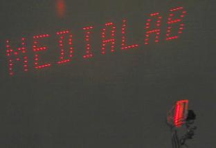
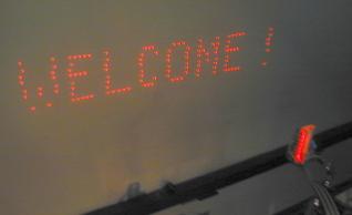
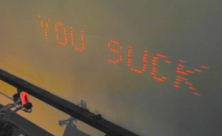
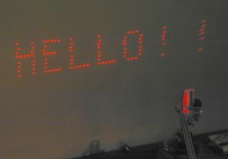
|
|
|
|
Figure 115: Example projections, and a close-up of TinyProjector prototype 9 in the dark (above). |
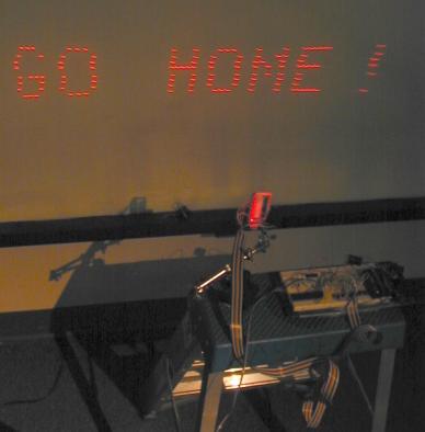

Since the jitter was almost gone, I conclude that the jitter problem must have been caused by mechanical slack of the hole in the plastic crank arm that holds the pushrod.
Logically, the still remaining jitter could be due to the connection of the pushrod with the mirror, which starts to get loose, too. To make the projection even more stable, I should make a new mirror with an aluminum holder. (But I have to unglue the servo arm from the motor, which is a pain, even with the Krazy glue remover.)
May 17, 2002
I tried to make a PIC software version that reads the serial port during the delay time before the blinking sequence. I didn't succeed.
Fixed other bugs in the PIC software, e.g., initial waiting time is now 16.5ms (16500 us).
Started designing an outer hull for the projector, which was going to be prototype 10.
May 18, 2002
I made a 3D model of all elements, in order to model the outer hull of prototype 10. Made two versions: hull with straight walls (TinyProjector2_all_v3.3dm), and hull with curved walls (TinyProjector2_all_v4.3dm) (Figure 116)
|
|
|
|
Figure 116: Designs for protecting the outside of the laser diode assembly. Straight (left), and curved walls (right) |
|
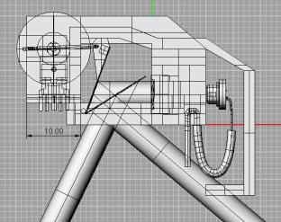
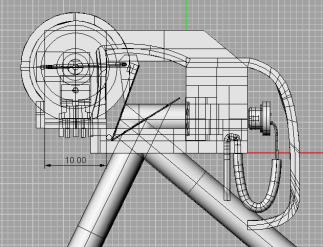
May 19, 2002
I refined the complete 3D model (TinyProjector2_all_v5.3dm), and created some 3D snapshots of hull (Figure 117). It is still not complete, since the motor compartment is not done yet.
|
|
|
|
|
|
|
|
|
|
|
|
|
|
|
|
Figure 117: TinyProjector prototype 10 |
|
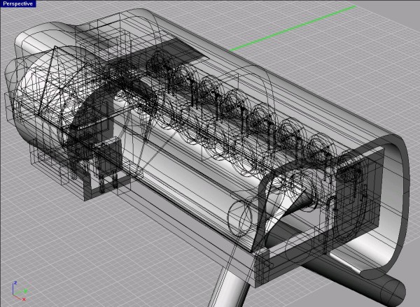
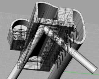

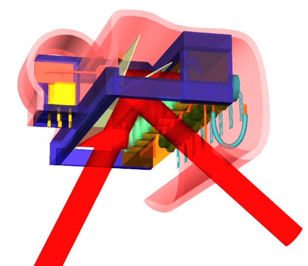
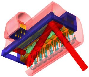
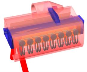
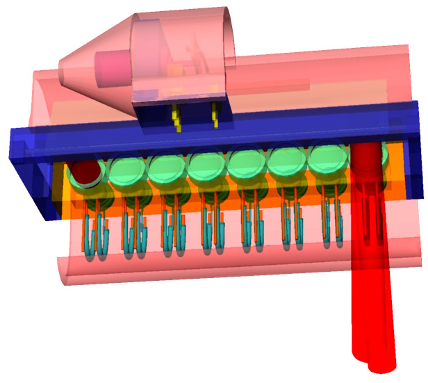
List of Figures
Figure 3: Key chain laser pointer (left), laser diodes (right)
Figure 5: Array of eight diodes, arranged in two rows, with secondary mirror.
Figure 6: Abacom/Linx low range RF transmitter/receivers (left, middle), PIC chip 16F84
Figure 8: From these key chain laser pointers, the laser diodes are extracted.
Figure 11: Acrylic holders for eight laser diodes; one row (left), two rows (right)
Figure 14: TinyProjector prototype 1
Figure 15: Four mirror surfaces per 360 degrees (left), five mirrors (middle), eight mirrors (right)
Figure 16: Eight-faced mirror with a linear laser array of 8 lasers, slightly displaced
Figure 17: First prototype with 8-faced mirror with Lego motor.
Figure 18: Linear array of 8 laser diodes, with single surface mirror mounted on a central axle
Figure 19: WES-2.4 servo (left), Hitec HS-50 (right)
Figure 20: Design with two rows of 4 laser diodes
Figure 22: Assembly with two rows of 4 mirrors
Figure 27: C code for TinyProjector prototype 2
Figure 28: Two projections: a row of "A" characters (left), and a row of high resolution "N" (right)
Figure 29: Drawings for poster
Figure 30: Working TinyProjector prototype 2
Figure 31: Final poster for Fall 2001 sponsor meeting
Figure 32: Me in my office, one of my work areas
Figure 33: Me demoing during the I:O sponsor open house
Figure 37: Red VCSEL component (preliminary)
Figure 38: Honeywell laser diode with aluminum tube holder and two lithium button cells
Figure 39: Mock-up with ABS square tube: front side (top), and back side (bottom)
Figure 40: New C code for second prototype, with simpler and clearer algorithm (new.c)
Figure 41: Pager motor Mabuchi J20WA (6mm diameter)
Figure 42: full rotation two-faced mirror balsa test assembly
Figure 45: Solid renderings by Quickslice
Figure 46: Wire frame models used by Quickslice
Figure 49: Fully assembled add-on to prototype two
Figure 50: Mirror holder, mirror, and motor
Figure 51: Schematic of prototype 3
Figure 52: Add-on and prototype 2 laser holder put together
Figure 55: Calculation of Theta Parallel for my “flat” laser diode
Figure 56: Maximum Theta used for a 7mm lens at a distance of 5mm
Figure 57: Minimum lens diameter for theta of 40 degrees, with lens focal length of 5mm
Figure 59: Projection angle and mirror angle
Figure 61: TinyProjector prototype 4 lens and diode holders
Figure 62: Theta parallel and perpendicular
Figure 65: Final C code for TinyProjector prototype 2
Figure 66: Casing of prototype 4 with smaller mirror axle and V-belt
Figure 67: Sketch schematic for reducing the 4.5V to 2.2V of the Lumex laser diode
Figure 68: Bourns 3299-102 potentiometer
Figure 69: Rubber belts and pulleys from LEGO would fit almost perfectly
Figure 73: 3D printed first casing, with a single lens and a single Lumex laser diode
Figure 74: Lens holder with side slit
Figure 75: 3D printed lens holder with side slit
Figure 81: Sweeping mirror assembly sketch with projection angle calculations
Figure 82: More sweeping mirror assembly sketches
Figure 83: Illustrating the angles of a sweeping assembly with a lens holder
Figure 86: Rotating mirror assembly with photodiode/IR LED
Figure 89: Motor Mabuchi MV2A, diameter 11mm
Figure 92: U piece with holes for prototype 6
Figure 94: Miniature ball bearings with an outer diameter of 3mm, for the 0.9mm axle
Figure 96: Smaller sweeping mirror assembly
Figure 99: Design of the mirror holder and the servo arm. It looks nice in the modeling software!
Figure 105: Holder with open back
Figure 106: Test of laser diode holder (left), completed holder (right)
Figure 107: Laser diode holders consisting of a double U shaped isolated wire
Figure 108: Final prototype 9 of TinyProjector
Figure 110: TinyProjector prototype 9 connected to a Palm Pilot via serial cable
Figure 111: Part of the signal of the photo diode during operation of TinyProjector
Figure 113: TinyProjector prototype 9 connected to a iDen cellphone via serial cable
Figure 115: Example projections, and a close-up of TinyProjector prototype 9 in the dark (above).
Figure 117: TinyProjector prototype 10
2/22/2003 6:28 PM